Continue to Site

Welcome to our site!

Electro Tech is an online community (with over 170,000 members) who enjoy talking about and building electronic circuits, projects and gadgets. To participate you need to register. Registration is free. Click here to register now.

  • Welcome to our site! Electro Tech is an online community (with over 170,000 members) who enjoy talking about and building electronic circuits, projects and gadgets. To participate you need to register. Registration is free. Click here to register now.

Voltage drop across inductor

Status
Not open for further replies.

pavjayt

Member
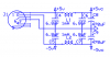
I have a simple circuit that has 4 op-amps in dual rail (±5VDC) configuration. On the power supply side, I have an inductor (**broken link removed**) on each line as in attached pic. I am using a regulated linear power supply set at ±5VDC and when I measure the voltage before the inductors, its ±5VDC and after the inductors its ±4.48VDC.

Any suggestions as to why its happening and how to fix this?
 

Attachments

  • powersupply.png
    powersupply.png
    29.4 KB · Views: 93
5V-4.48V=0.52V
So you are loosing about 1/2 of a volt.
The inductors have 4.9 ohms. Say 5 ohms to keep round numbers.
If you have 0.1 amps flowing through a 5 ohm resistor there will be 1/2 of a volt drop across the resistors.
My guess is the op-amps are drawing 100mA.

At a DC level the inductors are 4.9 ohms. Redraw your circuit with 4.9 ohm resistors in place of the inductors.
Thanks for your quick reply Ron. I should have noted my current consumption as well in my first post. The total draw on both rails is ~115mA which is inline to what you guessed. Wondering what would be good inductor selection over here?
 
Last edited:
Wondering what would be good inductor selection over here?
What are you trying to filter out?

You might look at the data sheet for the inductor line you picked. They might have a 100uH 0.4 ohm 1A version. It will cut your DC problem to 1/10, but not filter as well at high frequencies.

It is also possible to put the inductors before the regulators not after.
I am trying to keep out any noise out of the power supply rails before I use it for my high gain (~500) amplifier design.
 
I am trying to keep out any noise out of the power supply rails before I use it for my high gain (~500) amplifier design.
Inductors are problematic for that since they can resonate with the filter capacitors and can actually amplify any noise around that frequency.

Better to use a series ferrite bead (basically a lossy inductor) in series with the power along with a large electrolytic cap in parallel with a 100nF ceramic cap from the bead output to ground.
 
Status
Not open for further replies.

Latest threads

New Articles From Microcontroller Tips

Back
Top