Continue to Site

Welcome to our site!

Electro Tech is an online community (with over 170,000 members) who enjoy talking about and building electronic circuits, projects and gadgets. To participate you need to register. Registration is free. Click here to register now.

  • Welcome to our site! Electro Tech is an online community (with over 170,000 members) who enjoy talking about and building electronic circuits, projects and gadgets. To participate you need to register. Registration is free. Click here to register now.

Voltage dependent switching relay

Status
Not open for further replies.
I don't think you can use this for what you have stated. The battery connection is connected through to the load, and if you go fooling around with the voltage input, it will affect what is delivered to the load. Unless, that is, if you're only gonna to use it to operate the realy. You might post your intended circuit along with the details of your relay and let us look at it.
 
I am not using these controllers for my PV system they are spare. They have three 2 wire inputs; 12V from PV array, 12V battery , and Load. The PV charges battery unless over 13.8V when it shuts off the PV, Battery feeds load unless under 11.5V when it shuts off the load.

I would not use the PV input just battery connections and load output. This would work fine as is with the load powering ONLY a relay coil but 11.5V is too low and will damage the battery bank. 12.2V/12V is perfect

I can't post a circuit it is an encapsulated device.

The PV controller I am using for the system is much larger and better, these controllers are just left over from a system I never installed.

Relay coil is 230 mA 12V
 
Last edited:
I tried to obtain a schematic but couldn't, however the manufacturers reply (below) seems to have solved my issue (remember I DO NOT NEED THE PV INPUT)
Thanks guys it was your perseverence that led me her;


Hello,
Unfortunately, we cannot provide the schematic. You'll find, however, that if you crank up ( turn panel cutoff screw counterclockwise) the panel cut off voltage, the load cut off voltage will be increased. There's usually a 2 volt differential between load cut off and panel cut off. So by tweaking the panel cut off voltage , you can actually adjust the the load cutoff voltage.

Let us know how it goes.
tony
 
The controller switches OFF a relay for loads (up to 15 amps) if voltage falls below 11.5V
Try just adding a diode in series with the input to the controller. It should then switch off at 11.5V + 0.6V = 12.1V.
 
Well I'm afraid my idea was a total failure! Although I can get the Load to trigger OFF as high as 12.5V with the trimmer pot and although it then switches the power relay just fine I forgot to take account of one things;
#1 As soon as the inverter load is switched OFF the battery voltage springs right back above the set point and the power relay coil goes into constant oscillations. I can't believe I was dumb enough to have not considered that. The only thing I can think of is to insert a time delay so the relay coil will not re-energize for 10 to 15 minutes perhaps even 30 minutes thus giving the batteries time to re-charge a little either by daytime PV input or night time trickle charger input.

Any better ideas guys ?
 
As soon as the inverter load is switched OFF the battery voltage springs right back above the set point and the power relay coil goes into constant oscillations. I can't believe I was dumb enough to have not considered that.
Actually, you did....in post #7 :)
As was suggested in post #9, you could use a comparator with hysteresis.
 
Last edited:
Well that just makes me double dumb! LOL.

I would prefer not to mess with making circuit boards, something ready made would be nice.?
 
I would prefer not to mess with making circuit boards
Well in that case perhaps we could create hysteresis by using the relay change-over to add another diode in series with the first; then the set point would be ~ 12.7V. Unless the battery 'springs back' higher than that, the oscillation should be prevented.
 
Good greif. We had this problem before. What Ithink we ended up doing was switching a dummy load ontot the battery. Let me think about this over the weekend.
 
I have ordered ten 1 amp diodes but irrespective of what I install I think that the controller needs a larger hysteresis, a time delay or perhaps a dummy load as Brownout suggested. Kind of wasteful though ?
 
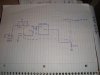
Yes, the dummy load was on a PV cell, and would be wasteful on a storage battery. But the good news is I still think we can make this work. Here is one idea, get a latching relay. Use one controller to turn it on. Set the trip voltage higher on that controller. Use a second controller to turn it off. Set that voltage lower. There is a potential problem with this scheme: the difference in battery voltage from loaded to unloaded might be more than what you originally wanted to set for the high to low voltage.

So here is a secone plan that solves that: what you need is an "incomplete" voltage divider, made of two resisters, but the connection to ground will be through a relay, which is disengaged while the system is "on". At the same time as the battery voltage drops and the system switches "off", the relay is made, completeing the voltage divider, and thus the battery voltage measured at the controller is divided, even though it rises, we can keep it below the level that keep the system off. When the battery voltage rises and the system truns on, the relay will break, and full battery voltage is measured at the system input.

Now the problem with that scheme is all the relays might not switch at the same time. We can come up with a scheme to make sure that happens.
 
Last edited:
Sounds good Brownout. The below link is what I have decided to try for now, mainly because it is only $8 shipped ! I am not clear as to if it always requires 12V to count up but I THINK I might be able to arrange that, anyway for 8 bucks I think it is worth a try. Probably won't get here from China until the new year now so you'll all get a rest from me.

**broken link removed**
 
I doubt delay timers will work. At the end of the time period, you have the same problem. It will do nothing more than slow down the oscillation.
 
Agreed but a 60 minute cycling oscillation will not burn out the relay contacts AND give time for the batteries to recharge (I think LOL) Maybe I should just go back to switching it on/off every day !
 
OK. Remember that with battery "Equalization charge V can go as high as 16V. That is; 4 stage PV controller charge rates are;

Stage 1. Bulk up to 13.7V.
Stage 2. Absorb 14.6V
Stage 3. Float 13.8V
Occasional stage 4. Equalize 15 to 16V
 
Here is a solution I'm pretty sure you can get to work. It requires one controller, two resistors and a dual, double throw, double pole relay. R1 and R2 form a voltage divider, which divides out the bump in battery voltage you get when the load disconnects. R1 should be connected to the NC contacts so it's shorted while the battery is connected to the load. R2 is connected to the NO contacts. When the realy is energized, R1 and R2 divide the input voltage down to a level that prevents the controller from reconnecting. The values depend on how high the battery voltage spikes up when disconnected. I can guess a value of 1K for R1 and 10K for R2 might be a good place to start. Capacitor C1 shold help prevent the input voltage from spiking up while the relay is pulling in. The other part of the dual realy connects the battery directly to the load ( does not go through the controller ) That connection isn't shown on the drawing.
 

Attachments

  • DSC00871.JPG
    DSC00871.JPG
    2.3 MB · Views: 137
Last edited:
PS: C1 will be critical to the correct operation of this circuit. It must be large enough to absorbe the spike. However, when connecting the battery, excessive current could flow into it, possibley damaging it. You'll need a series resistor to limit intial current. Again, the value will be determined experimentally. Another optoin might be to connect it across the relay coil to keep it energized long enough to pull in the contacts. On second thought, I think that's a better option.

Also, it occured to me that R2 can be connected directly and doesn't need to be switched. R1 should also be connected to NO contacts, not NC as shown.
 
Last edited:
Status
Not open for further replies.

Latest threads

New Articles From Microcontroller Tips

Back
Top