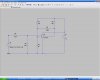
I have a photo voltaic system (12 volt 1000W max) with 120 volt shore supply and 120V inverter supply. Presently I have a manually switched DPDT relay which operates well but I would like to automate it to switch from battery bank (inverter) to shore supply below about 12.2 volts. As an electrician I am not brilliant at soldering electronic circuits so am thinking I could use an SSR with a series zener input to switch the DPDT relay automatically
Relay coil draw is less than one amp I am hoping that a series 12v Zener across the SSR input and fed with battery voltage with perhaps a voltage dividing pot also in series to make it all adjustable would work.??
I am not sure though that the 2 volts or so normally required to operate the SSR might already be present even when the voltage is below 12V
Any advice greatly appreciated
Thinking about this I am also concerned that the Zener once fired will simply cause the relay to latch or oscillate even if the voltage drops below 12.2V ?
Last edited:
")