Continue to Site

Welcome to our site!

Electro Tech is an online community (with over 170,000 members) who enjoy talking about and building electronic circuits, projects and gadgets. To participate you need to register. Registration is free. Click here to register now.

  • Welcome to our site! Electro Tech is an online community (with over 170,000 members) who enjoy talking about and building electronic circuits, projects and gadgets. To participate you need to register. Registration is free. Click here to register now.

voltage and current display on lcd using pic18f4520

Status
Not open for further replies.

stereovestro

New Member
hi there.....

im currently working on mini project for my car. ok, i would like to display voltage and current of my car onto a lcd 16x2 RT1602C using pic18f4520.

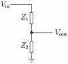
1. what type of voltage and current sensor can i use?( car voltage 12v battery)

2. is pic18f4520 has an inbuilt analog to digital or i need adc ic to connect it externally?

3. im using mplab ide v 7.6 for the coding. i have pic18f4520 with components pack connected to lcd and its working( tested with simple lcd code) is there any link in google for the code that i could alter it?

thnx.....
 
Voltage sensor - maybe consider connecting the battery to a potential divider (1:4 ratio) to give you a 0-20 volt battery range down to a 0-5v range for the PIC (also consider filtering, a zener to protect against over voltage and a cap to smooth the nasties a bit)

Current sensor will be a pain in the neck - especially if you are intending to measure the charge and discharge of the battery.

Consider using a clamp on type of current measuring device for any cable - there are some large currents flowing through the battery circuit. Something like a ferrite filter modified with a low gauss flux sensor in the gap works.
 
A LONGGG! ago project in EPE (before it was called that), back when the LM3914 LED display chips first came out, measured car battery charging and discharging by using an opamp to simply monitor (and amplify) the voltage drop across the existing car battery earth strap. Nice easy solution, requiring no modification, and no extra voltage drop.
 
ok so pic18f4520 has internal built in analog to digital. so i need not use adc ic?

as for the code, im working on it. already being able to display the introduction on the lcd eg. welcome.

i'll get bck here again.

thnx!
 
sensing voltage

ok before start off with high voltage, i was thinking ok 9v first.
i use voltage divider to sense the supply voltage and display it on the lcd.

1. when i decrease the power supp, the lcd's getting dimmer.
2. is it possible to display the supply voltage on the lcd using this method?

here's the attachment.

vin is 9v.
z1 3kohm
z2 330ohm
vout 5v(to microcrontoller)
 

Attachments

  • Impedance_Voltage_divider.png
    Impedance_Voltage_divider.png
    2.8 KB · Views: 373
and the code for only displaying the following.

#include <p18f4520.h>
#include <delays.h>

void Init_LCD(void);
void W_ctr_8bit(char);
void W_data_8bit(char);
void Delay_1kcyc(void);

#define LCD_DATA PORTD
#define LCD_RS PORTBbits.RB1
#define LCD_E PORTBbits.RB2

unsigned char LCD_temp, i,j,k,m;
char MESS[15]= " HYBRID GOLFCAR";
char MONI[14]= " monitoring...";
char VOLT[10]= " VOLTAGE &";
char CURR[8]= " CURRENT ";


void main()
{

ADCON1=0xF;
TRISB=0b11111001;
TRISD=0;

Init_LCD();
for (i=0; i<15; i++)
{
W_data_8bit(MESS);
}


W_ctr_8bit(0b00000001); // clear previous screen
W_ctr_8bit(0b10000010);
for (i=0; i<14; i++){ // Output message "hybrid golfcar" to LCD
W_data_8bit(MONI);
}


W_ctr_8bit(0b00000001); // clear previous screen
W_ctr_8bit(0b10000010);
for (i=0; i<16; i++) // Output message "voltage &" to LCD
W_data_8bit(VOLT);

W_ctr_8bit(0b11000100);
for (i=0; i<8; i++) // Output message "current" to LCD
{
W_data_8bit(CURR);
}

for (i=0; i<5; i++)
{
Delay1KTCYx(50);
}

}


void Init_LCD(){
W_ctr_8bit(0b00111000);
W_ctr_8bit(0b00001100);
W_ctr_8bit(0b00000110);
W_ctr_8bit(0b00000001);

}

void W_ctr_8bit(char x) {
LCD_RS =0;
LCD_E=1;
LCD_DATA=x;
LCD_E=0;
Delay10KTCYx(10);
}

void W_data_8bit (char x) {
LCD_RS =1;
LCD_E =1;
LCD_DATA = x;
LCD_E=0;
Delay10KTCYx(10);
}
 
ok before start off with high voltage, i was thinking ok 9v first.
i use voltage divider to sense the supply voltage and display it on the lcd.

1. when i decrease the power supp, the lcd's getting dimmer.
2. is it possible to display the supply voltage on the lcd using this method?

here's the attachment.

vin is 9v.
z1 3kohm
z2 330ohm
vout 5v(to microcrontoller)

Hi,

Your microcontroller and LCD require a regulated +5V supply i.e. voltage fixed at +5V. So the +9V would supply a LDO (low drop out regulator) directly and you can scale the analog input voltage so that , for example, +10V to +12V (battery discharged at +10V?) gives 0 to +5V. The pic analog input voltage should not go higher than the PIC supply voltage.
 
Last edited:
ok here's my latest program. i could display voltage but in binary.there a potentiometer that could adjust the voltage. 1024 is displayed on my lcd which equivalent to 5v.

i would like to display the current as well.
is there any way that i can display 5v instead of 1024?


#include <p18f4520.h>
#include <delays.h>
#include <stdlib.h>
int result;
void Init_LCD(void);

void W_ctr_4bit(char);
void W_data_4bit(char);

#define LCD_DATA PORTD
#define LCD_RW PORTAbits.RA2
#define LCD_RS PORTAbits.RA3
#define LCD_E PORTAbits.RA1

unsigned char LCD_TEMP, i;
char MESS[16]= "voltage control";
char MESS2[6]= " A";

void InterruptHandlerLow(void);

#pragma code InterruptVectorLow= 0x018
void InterruptVectorLow(void) {
_asm
goto InterruptHandlerLow

_endasm
}
#pragma code
#pragma interruptlow InterruptHandlerLow
void InterruptHandlerLow()
{
if(PIR1bits.TMR1IF){
Delay10TCYx(1);
ADCON0bits.GO=1;
while(ADCON0bits.DONE);
result= ADRESH*256+ADRESL;
//result>>=4;
PORTB=result;
W_ctr_4bit(0xc0);
for(i=0; i<4; i++)
{W_data_4bit(MESS2);
}
W_ctr_4bit(0xc0);
itoa(result,MESS);
i=0;
while(MESS)
{
W_data_4bit(MESS);
i++;}
TMR1H=0x0b;
TMR1L=0xdc;
PIR1bits.TMR1IF=0;
}
}
void main()
{
TRISD=0;
TRISA=0b11110001;
TRISB=0b11110000;
ADCON0=0b00000001;
ADCON1=0b00001110;
ADCON2=0b10000100;

INTCONbits.GIE=0;
Init_LCD();
for(i=0;i<15;i++)
{
W_data_4bit(MESS);
}
PORTB=0b00000110;
RCONbits.IPEN=1;
IPR1bits.TMR1IP=0;
TMR1H=0x0b;
TMR1L=0xdc;
T1CON=0b11110001;
PIR1bits.TMR1IF=0;
PIE1bits.TMR1IE=1;
INTCONbits.GIEL=1;
INTCONbits.GIE=1;
while(1);
}
void Init_LCD()
{
Delay1KTCYx(15);
W_ctr_4bit(0x03);
Delay1KTCYx(5);
W_ctr_4bit(0x02);
W_ctr_4bit(0b00101000);
W_ctr_4bit(0b00001100);
W_ctr_4bit(0b00000110);
W_ctr_4bit(0b00000001);
}
void W_ctr_4bit(char x)
{
LCD_RW=0;
LCD_RS=0;
LCD_TEMP=x;
LCD_TEMP>>=4;
LCD_E=1;
LCD_DATA=LCD_TEMP;
Delay1KTCYx(1);
LCD_E=0;
Delay1KTCYx(1);
LCD_TEMP=x;
LCD_TEMP &=0x0f;
LCD_E=1;
LCD_DATA=LCD_TEMP;
Delay1KTCYx(1);
LCD_E=0;
Delay1KTCYx(1);
}


void W_data_4bit(char x)
{
LCD_RW=0;
LCD_RS=1;
LCD_TEMP=x;
LCD_TEMP>>=4;
LCD_E=1;
LCD_DATA=LCD_TEMP;
Delay1KTCYx(1);
LCD_E=0;
Delay1KTCYx(1);
LCD_TEMP=x;
LCD_TEMP &=0x0f;
LCD_E=1;
LCD_DATA=LCD_TEMP;
Delay1KTCYx(1);
LCD_E=0;
Delay1KTCYx(1);
}
 
ok so pic18f4520 has internal built in analog to digital. so i need not use adc ic?

as for the code, im working on it. already being able to display the introduction on the lcd eg. welcome.

i'll get bck here again.

thnx!
Well you've still got a HECK of a problem measuring current.
Any shunt with a small enough resistance that it won't overheat when charging (which can be >100A if your batt was run down) or starting (which can be hundreds of amps), or drop the voltage so much that the vehicle won't operate properly at high charge/discharge rates, will be far too small for the PIC to measure. It's also bidirectional, and the PIC cannot measure negative voltages even if the shunt is ground-referenced; nor can it even be exposed to that voltage on the pin.
 
display voltage

well as for now i can display voltage of the microcontroller (max 5v). i can adjust it using potentiometer.

i would like to maximise the voltage to, say, 12v.(using 12v batt)
what need to be done to get the reading of 0v to 12v on the lcd?

as for the current; get the voltage/resistance (o.o1ohm) and display it on lcd.

sounds easy but harder than it seems to be.
help is needed.
thank you.
 
Status
Not open for further replies.

Latest threads

New Articles From Microcontroller Tips

Back
Top