Continue to Site

Welcome to our site!

Electro Tech is an online community (with over 170,000 members) who enjoy talking about and building electronic circuits, projects and gadgets. To participate you need to register. Registration is free. Click here to register now.

  • Welcome to our site! Electro Tech is an online community (with over 170,000 members) who enjoy talking about and building electronic circuits, projects and gadgets. To participate you need to register. Registration is free. Click here to register now.

Voltage after inverter

Status
Not open for further replies.

LarsNor

New Member
Hi, gentlemen.
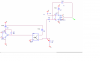
I faced with problem i can't explain. I have PWM signal after optocoupler( 0-5 V) and i need to invert it for using in motor driver, but after inverting PWM signal is mush less than forwed PWM. I tried to increase R of feedback but it doesn't help. Who can help or advice with it?
 

Attachments

  • 4.png
    4.png
    13 KB · Views: 116
  • 5.png
    5.png
    49.3 KB · Views: 116
What is the opto-isolator doing in this circuit?
 
...Condition of the project, for safety

The way you are using the opto, there is no isolation between the circuit on the left and the one on the right, hence the opto does nothing!
 
May me it exists another way to invert PWM, easier? I tried to use in circuit inverter 74HC04, but got logic output, i'm newbee in this topic, and don't understand what happens
 
There are many ways to invert the logic.
1)Shown below will work.
2)Swap LM393 pins 2&3.
upload_2017-4-25_8-29-34.png

The inverter you are using:
I can not read the part number. Most of these parts do not have the ability to pull the output to either supply voltage. (0V or 5V) The data sheet will tell you how many volts are needed. (0.5V or 1V this is very dependent on which part and what the load is) Now you have a 2K load and 4V so 2mA load. You need a "R-R" output amp.

It is not good to leave a input not connected. Back to the (+) input. I know your SPICE is working but.....in the real world this results in strange things happening.
 
U22 is a TL081 (I think), it has a 5v supply.
The TL071/72/81/82 are not rail to rail, so what you see on your "oscilloscope" is correct.

JimB
 
I tried to use in circuit inverter 74HC04, but got logic output
What's a "logic output"? :confused:
Change R37 to 5kΩ.
With it 5V supply the 74HC04 will give you a 0-5V signal output.

If all you want is to invert the signal, just put R37 in series with the collector (between power and collector) of the opto coupler output with the emitter to ground.
 
Status
Not open for further replies.

New Articles From Microcontroller Tips

Back
Top