i downloaded the datasheet and went through it before this.
but, i do not quite understand how the circuit works as much as i want to
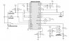
for example, what is the purpose of placing the capacitor C4, C3 and R4 there..
also, the switches S1, it's a push-to-make switch right?
does that mean that if i press once, it will start, and paused when pressed again?
please help.....