Continue to Site

Welcome to our site!

Electro Tech is an online community (with over 170,000 members) who enjoy talking about and building electronic circuits, projects and gadgets. To participate you need to register. Registration is free. Click here to register now.

  • Welcome to our site! Electro Tech is an online community (with over 170,000 members) who enjoy talking about and building electronic circuits, projects and gadgets. To participate you need to register. Registration is free. Click here to register now.

visual identification /recognition ---of a 12 volt one watt zener diode already attached to a old ci

Status
Not open for further replies.

ZAMDUDE

New Member
Hi ----
This is 17 th attempt --many forums cannot help --get really annoyed --

The question is very straightforward ---VISUAL ID of those tiny glass zeners ==7 yrs later -still stuggling to id a 12 volt one watt zener
on a mountain of scrapped pc /& various circuit boards ---

OK --have built many circuits ---in the backwoods --guitar amps /timers /alarms --
have studied all the basics for many years --
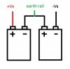
A simple straight forward battery charger circuit ----died when the polarity output was accidently /stupidly crossed--
fried the only 7128 voltage regulator chip I had --
but found another ----
oops ---Zener diode --required --
so after weeks of scouring circuit (old ) boards ----
have found many zeners --but voltage /coded /numbers --are almost impossible to --read --

cAN ANYONE show me how to VISUALLY ID THE 12 VOLT ZENER ?==
IF not --no problem ----theory on forward /reverse breakdown /bias is NOT required ---
just a color or number or code app that id,s these Zeners --will be much appreciated ---
(cannot find a chart or online Zener id /codehieroglyphics unravelling method )

Most grateful if anyone can see these little nightmares ---I give up !
regards --Zamdude --Africa
 
There is no one-size-fits-all answer to your question. Different manufacturers have their own different ways of coding diode values/types.
If you're lucky, part of the code will include digits corresponding to the breakdown voltage. For example, KDZ6_8B by Rohm is a 6.8V zener diode :), whereas a 6.8V zener diode by Motorola is coded 1N4736 :( .
 
Many Thanks ALEC --APPRECIATE --

So what markings will 12 VOLT ONE AMP zener --by Motorola or other manufacturerers --

read as ? what color ---what do they look like ?

Can you post me a color FOTO -- of a zener --( a comparison to a standard "lookalike diode "
ie I am told a Zener is "fatter & longer "" with some brands having different colours /markings etc

hOW TO VISUALLY id THESE DIODES IS only by that symbol ------
but they could be ANY VOLTAGE /WATTAGE

Surely after 100 yrs of electronic innovations --SOMEONE would have made it EASIER to id ZENERS??

(I HAVE read thousands of complaints by so many people over the years --- codes & color /appearance
seems to baffle all --
and that twin battery /reverse meter leads /resistor diode in series method --is extremely unreliable & confusing

so the numbers and colors are best --
a color FOTO would help ---(picture paints a thousand complex jargon filled descriptions

and its only a battery charger circuit !! what A MISSION !!( BUT its for a burglar alarm system --12 volt
--extremely necessary for burglars ---and NOT for my own amusement as a expert once chided me on another forum

--just wanting to learn ---that's all !!
regards zamdude
 
Colour is not useful as a universal type/value indicator. Again, it can vary from one manufacturer to another. Also, colours on components, particularly those which get hot in use (as zeners and resistors can), often change or fade in time. I am not aware that zener diodes are deliberately coloured differently from normal diodes by any manufacturer. If you want to check, I suggest you visit various manufacturers web-sites and compare diode images.
Circuit boards sometimes helpfully have component identifiers such as "ZD3" silk-screened on them.
 
So ---I have no foto ?---u cannot give me a foto of a Zener 12 volt one amp ? any make or model will do --
mind you I have downloaded a thousand images of Zeners ==don't appear any different to all other orange /black diodes
--just the symbol says its Zener ====that's all ---great mystery continues !==7 year s ---no one can VISUALLY ID these Zeners !
Testing with a battery ----yields almost identical reverse /voltages --circs 4 . 6 -5 .2
and forward gives steagy 11 .99 volts
ON EVERY SINGLE DIODE --even black power diodes have reverse readings ---
so how can a zener possibly be different to any glass diode ----IT MUST BE DIFFERENT for visualpurposes --not camouflaged
---or identical colors /readings ---
I have one which says Z -- and a 9 or 6 printed on it ----BUT NO WATTAGE INDICATED! could be any value watts
another reads BZY -- Numbers are cryptic code
another reads 8 - 6 ----no indication its voltage ----

best to order a IN 4742 from USA wAIT 6-8 WEEKS --I am told this is a 12 volt I amp Zener ---but no illustration shown -
as always --just a group of tiny diode lookalikes --(all look the same )
glad I /m not an electronic engineer ---------madness !
Then maybe I can see how it appears ----but that's no guarantee its not a recent manufacturers total change in appearance ?
I give up ---back to the circuit board
 
u cannot give me a foto of a Zener 12 volt one amp ?
Sorry, I don't have one. I would need to google for one, the same as you would.
I have downloaded a thousand images of Zeners ==don't appear any different to all other orange /black diodes
That reinforces what I said about coding/colour. I don't have the time or inclination to look at 1000 images.
so how can a zener possibly be different to any glass diode
The silicon doping differs. The difference is not visually discernible.
 
We order a zener diode with its part number, we do not attempt to find one in a bucket full of old diodes. The part number has a datasheet that lists its maximum power, its maximum current and its recommended current that it is tested at in the factory. Most 1/2W zener diodes are in a DO-35 glass package but a few 1W ones are in a larger DO-41 glass package.

They all look the same but I have not used a zener diode for many years, I use voltage regulators that have a part number or voltage stamped on them.
 
1N3311B DIODE ZENER 12V 50W DO5
1N3311B.JPG


upload_2017-3-17_19-1-58.png


1N5349 DIODE ZENER 12V 5W AXIAL
SurmeticP6KE_6.8A.jpg
 
A simple and rough method:
If you have a variable power supply and a multimeter, you can characterize unknown diodes.

Add a small resistor in series with the zener. Connect them both to the variable supply and start increasing the output voltage slowly while monitoring the diode voltage with the DMM.

When the voltage stops increasing or increases very slowly, that is your zener voltage.

If the voltage goes beyond 30 volt, most likely it is not a zener diode but something else.
Note, there are zeners with voltages above 30v but are not very common.
 
Finally ---brilliant idea ----thankyou Schmitt trigger

TRIED your method ----perfect -------voltage stops /slows with Zeners !
Now I understand what "clamping "the voltage means ""--
ie fixes THE volts to prevent overcharging ----the battery --a simple valve control !

many thanks ---have--another vexing issue --

a TDA 2006 amp --- built 3 OF them ---as a preamp for my guitar --& simple PA mike amp ---
but the circuit schematic ---appears to differ from the actual etched circuit board I made

something wrong ---a mike or guitar jack input --initially sounds ok --but quickly distorts --
Its rated 15 watt -------
have tried every which way to correct it ---still growls annoyingly --my voice varies in pitch
---eventually it dies --then suddenly awakens sqwauk ---then ok --then zip ! weird --
( the other bigger TDA AMPS I made --all work fine ---

but this 2006 --something wrong with circuit components or configuration--

look at both SINGLE 12 V Supply circuits shown in the PDF --
a 22 MF cap is missing in the lower circuit --some values are altered -----maybe my 30 watt speaker (4 ohm )
is overloading the 2200 cap out put --or maybe faulty IC ?( INPUT is a clean guitar single coil jack --no FX)
appreciate if you can get this circuit to work ?
if not ---many thanks for the Zener clarification ---
Zamdude
 
The datasheet for the TDA2006 shows an output of 12W into a 4 ohm speaker with horrible 10% distortion with a 24V supply. Its power is 2.8W into 4 ohms with 10% distortion with a 12V supply. Its power is 8W into a 4 ohm speaker with low distortion and a 24V supply or is 1.8W with low distortion and a 12V supply. The schematics and pcb designs in the datasheet are for a dual-polarity supply and for a single-polarity supply so of course they are a little different.

A TDA2005 has two amplifiers that are in a bridge so that it can produce about 12W with low distortion into 4 ohms and a 12V supply. The datasheet of the TDA2006 shows a bridged amplifier with two ICs driving an 8 ohm speaker.

Since your voice comes and goes then it is probably overheating and shutting down to protect itself. Maybe your heatsink is too small or is enclosed.
 
Well --I think you are spot on again --thanks Audio ---
I have a dozen or so TDA 2006 new chips --imported from California years ago --MUST be a way of reducing that distortion ?

Yet the tda 2005-- DUAL ic amp I built diy ---years ago --
is still superb --used as a pre-amp --into a FENDER amp ---5 yrs no problem!
and
The TDA 2040--(24 VOLT 24 WATT amp I built same time ---(two 12 volt batteries -series)
performs sweetly as a music booster amp in my car --

Yet the TDA 2006 is NIGHTMARE --------made so many circuits ---ALL growl ominously ---even low signal input distorts
You have confirme my worst fears --no wonder the data sheet is stamped " obsolete products"!!

Yet the very first schematic that appears ----(says--" typical application circuit )--LOOKS very easy to create ?
very simple --few components ---so I will give it a go ---build this from scratch !!)

( I built Darlington pair TIP 31 & 32 amp ---very simple circuit---zero distortion --great mike amp )
for the school kids to mess with ---they were delighted)----no distortion --but HUGE heat sink required
(loud voices--of screaming kids heat up the TIP power transistors )( mike made from reverse speaker thru tiny audio transformer)
more sensitive than all my commercial bought microphones !--

at least --tab /cooling sink--heat is a sure fire sign --the TIPs are working --!
TDA --2006 ---NEVER gets warm ---despite removing Huge heat cooling fins---4 inches square aluminium )
something I got wrong I suppose ---but wont give up --

OK will give that tda---2006 another final attempt --as all the others work very well -2005 ---2014--2012 etc --
just replace/ use a brand new California IC ---Pity to throw em out --?
( bATTERY charger circuit you gave me ---is a star performer ----even with my crazy head to tail -chain of zeners all joined in series -
till I got 13 .8 volts output ----down from 16 volts ------success is worth the sweat /experimenting --

but I have ordered (reluctantly _ ) a whole range-of 1 - 5 WATT 12 volt Zeners ---from USA ---6 -8 Weeks agonizing wait--
Most grateful for all your advice --research ---really appreciate
zamdude
 
The distortion from most amplifier ICs including the TDA2006 is very low until its output power begins to cause clipping when the output voltage swing becomes as high as it can and the waveform has flat top and bottom parts approaching a squarewave.
Of course the output power before clipping is reduced when the supply voltage is reduced and your 12V supply for a TDA2006 is the lowest that is shown on its power vs supply voltage graph.

I have no idea why you are using power amplifiers as pre-amplifiers.
 
Thanks Audio guru---
Can you explain what exactly is meant by SPLIT POWER SUPPLY ?
2 x 6 volt batteries --with MID connection to ground ?
or 2X 12 VOLT batteries ---mid connection to ground ?
( The datasheet says 12 volt + /minus supply (SINGLE supply -yet I think its split supply (2 x 12 volt batteries in series)
mid connection goes to that weird T shape ground icon ---
the other goes to negative---
or does one use 2x 6VOLT batteries in series

Can you show me tda 2006 circuit ---with relevant battery /voltage hookup ? (diagrammatically )?
( That does not crackle &p pop?

some SCHEMATICS show only 12 volt supply to pin 1 ---tda 2006
(spent 24 hrs building another circuit --less components ---
still distorts -----
The bridge (two IC AMP ) shows split supply AND single supply

but 5 amps later ---ALL are weak or crackly ---despite FAITHFULLY copying EXACT schematics --over & over
( some show 100 MF Cap --in parallel with 104 ceramic caps (shown with dotted line )
connected to pin 3 (negative )
not sure if this is alternative arrangement --or together /?

Appreciate any clarification /diagram --of the correct (single ) IC 2006 connection

Most grateful for your patience ----I will get it right eventually !
Best regards ---- Zamdude
 
Can you explain what exactly is meant by SPLIT POWER SUPPLY ?
The signal on a speaker must swing positive and negative. But an audio amplifier with a single positive supply has an output with DC always on it which is bad for a speaker, so an output coupling capacitor is used to feed the speaker with AC that swings positive and negative. A split supply has a positive voltage and a negative voltage then the output of the amplifier can swing positive and negative then no output coupling capacitor is needed.

[2 x 6 volt batteries --with MID connection to ground ?
Yes, then the amplifier output to a speaker can swing up to about +4V and down to about -4V.

or 2X 12 VOLT batteries ---mid connection to ground ?
Yes, then the amplifier output can swing up to about +9V and down to about -9V.

The datasheet says 12 volt + /minus supply (SINGLE supply -yet I think its split supply (2 x 12 volt batteries in series
+/- 12V is positive 12V and a negative 12V for a total voltage of 24V, it is a split supply. A single positive 24V supply will work the same if a coupling capacitor feeds the speaker and if the input of the amplifier is biased at half the supply voltage.

mid connection goes to that weird T shape ground icon
Of course the mid voltage must be a common (ground) so that the amplifier output swings up and down.

or does one use 2x 6VOLT batteries in series
Then it is a single polarity positive 12V supply.

Can you show me tda 2006 circuit ---with relevant battery /voltage hookup ? (diagrammatically )?
( That does not crackle &p pop?)
An audio amplifier that is wired correctly and that is not defective does not crackle and pop. Maybe your circuit has a connection that is loose and sounds cause it to make and break the connection.

some SCHEMATICS show only 12 volt supply to pin 1 ---tda 2006
The spec's, schematics and pcb designs on the datasheet show a +12 and -12V split supply and a positive 24V supply. Its output power is shown on a graph to be very low with only 12V.

(spent 24 hrs building another circuit --less components --- still distorts ---
Any amplifier distorts if its output is clipping because the input level is too high. Any amplifier built with a poor pcb design oscillates at a high frequency which causes severe distortion.
The datasheet shows proper schematics and recommended pcb designs.

The bridge (two IC AMP ) shows split supply AND single supply
It shows only a split supply. A single supply can be used if the amplifier inputs are biased at half the supply voltage.

but 5 amps later ---ALL are weak or crackly ---despite FAITHFULLY copying EXACT schematics --over & over
( some show 100 MF Cap --in parallel with 104 ceramic caps (shown with dotted line )
They also show a dotted C8 and R5. The datasheet tells you that all of them are to prevent oscillation.

connected to pin 3 (negative) not sure if this is alternative arrangement --or together /?
The datasheet shows that pin 3 is grounded (0V) with a single supply and is at the negative supply with a split supply.[/quote][/quote]
 
Thanks Audio ---
but your hi tech explanation of swinging up &down --is way over my head ---
All I need is a diagram --showing HOW the batteries --(single 12 volt )or 2 x 12 volt --or 2 x 6 Volt

can be correctly coulpled to this nightmare growler ---ALL connections are solid --triple tested
I have made so many -- driving me bonkers ---all distort exactly the same ! 7 units made --
all identical -----the twin TDA Bridge are the worst -----
this is all due --I am certain --to INCORRECT VOLTAGE SUPPLY !
this happened years ago ----
I got a hookup diagram from a fella -------which clarified it all ---
ie TWO BATTERIES ------ with the MIDWAY connection to the strange T SYMBOL --that keeps me baffled
---
I seriously need a schematic showing the exact Battery type ( 12 volt single --or 12 volt double --or 6 volt double -series of batteries)

How on earth does a single 12 volt battery be ""SPLIT VOLTAGE ?"--- where does the THIRD connection go to ??
single 12 volt lead acid battery has 6 cells ----only TWO TERMINALS ---- so---
HOW can 12 volt be SPLIT ---into 3 ?
OR is it a serious misprint ?
( I have only ONE 12 VOLT battery --fully charged --new )
do I have to purchase another m/cycle battery --? to get this nightmare to amplify voice ?

CAN I USE TWO PM9 VOLT radio batteries (ie the cardboard PM 9 type?)( maybe you have different type batteries in your area ?

here are two schematics --I tried to use --years ago ----
still ---distortion ruled!
must be some trick to get this working --I have dozens of TDA 2006 ic .s ---
pity to smash em all ?---nothing seems to work -

A simple clear schematic with red & green connections from ONE A OR SEVERAL BATTERIES
will eliminate a thousand complex tech jargon phrases ----(square wave oscillation ) swinging voltage from pos to neg --
on DC supply ---is frightening !! ---AC sine wave oscillates at 50 hertz ----
but DC VOLTAGE swing up & down ---pos to neg --in this circuit --sounds awful !
apologies
just want to build a 12 watt amp ---for ANY weak or loud voice signal input --
 

Attachments

  • THE 12 O 12 SERIES GND COMPLEX BATTERY CONN.jpg
    THE 12 O 12 SERIES GND COMPLEX BATTERY CONN.jpg
    4.7 KB · Views: 194
  • AmpSchematic_zpsec544a83.jpg SKETCH FOR THE FORUM ---WRONG BATTERY HOOKUP --.jpg
    AmpSchematic_zpsec544a83.jpg SKETCH FOR THE FORUM ---WRONG BATTERY HOOKUP --.jpg
    45.5 KB · Views: 210
Your amplifier was a copy of a very poorly drawn schematic. I show my corrections.
The amplifier is supposed to drive a speaker with power but the power from those cheap little 9V batteries is much too low. A bunch of AA alkaline batteries might last for a few minutes at full power.

This is a power amplifier designed to be driven from a radio tuner or MP3 player. A microphone has such a low level that it must feed a pre-amplifier circuit that feeds this power amplifier.
 

Attachments

  • TDA2006 amp.png
    TDA2006 amp.png
    307.3 KB · Views: 433
Thankyou again Audio ----
You have redrawn the circuit --EXACTLY the same as I did -----years ago ---
The schematic does not show the "skip over " on R1 --and Pin 3 does not go to neg earth ==ok
I redtified this years ago with help from this forum ---

However ------your corrected drawing is what I had been using for years!!

it SIMPLY KEEPS DISTORTING !!!!!------
and one cannot connect 2X 12 VOLT batteries --however strong /weak or expensive --
across this circuit you hav drawn for me --
I have constructed DOZENS ----of your corrected circuit ----they have never given clear audio out put !
crackly /muffled /but occasionally loud voice --then bang fizz ---gone --overheating TDA2006
( BURNS FINGERS ) ---
TWO 9 VOLT batteries in series ---with the 3RD (MIDWAY connection --as it should be labelled to that odd T REF GROUND
( A very misleading term )---
ie its two 12 volt circuits --IN one !!
but no matter what ---batteries you use (twin 6volt ) or twin 12 volt ) with 3 rd MIDWAY terminal --
the tda grumbles forever --

The ONLY WAY FORWARD ---HERE ---
IS FOR YOU TO BUILD THIS " CORRECTED " CIRCUIT ---YOURSELF !
this way --you will see what I am saying all along -------and your expertise /genius /years of learning -
--will solve this monster -------
IBEG YOU TO HAVE ago --use a breadboard or another sophisticated method you guys use --
to test ?prove the circuits ----you have oscilloscopes and other superb devices I am sure ?

Local Varsity offins told me to p****** off -----their electronic labs /experts are NOT @ my disposal !
many forums years ago --got fed up with my badgering them about this 2006 --!
got humiliated /insulted with facetious /sarcasm --by the truckload 1

However ---I will not give in -----and your patience is very impressive !
Please help --------? construct this demon --and I can put it to rest --once & for all !

My latest attempt --was to trace the actual "printed circuit squiggle snakes"-
superimposed onto 1/2 mm thick brass shim plate ----
cut out each circuit "snake ? painstakingly ----super glue to thin plywood block --
---voila --press and clean brass ------light sanding --solder in all components

TDA --2006 ----no matter how improved my contact surfaces --triple checked contact /components are
refuses to amplify guitar /voice /even fx input --all roar like sea surf ------

Please try to construct it your way --if you are successful ( I know you will find the fault )
I will be eternally grateful -
but your patience has run out by now --cannot blame you guys --
Really appreciate all the help you gave me --(learnt another quantum leap )
regards ----Zamdude -----or Zendode ----
 
You said the IC burned your fingers. then either it is playing loudly driving speakers with an impedance too low (less than 4 ohms) with a heatsink that is too small or it is on a poorly designed pcb causing high frequency oscillation.

I have made hundreds of IC audio amplifiers but never with a Chinese IC (too much rice in them) or never with with a Italian one (too much pasta in them). The TDA amplifier ICs are made by ST Micro who I think are Italian.
 
Status
Not open for further replies.

Latest threads

New Articles From Microcontroller Tips

Back
Top