Continue to Site

Welcome to our site!

Electro Tech is an online community (with over 170,000 members) who enjoy talking about and building electronic circuits, projects and gadgets. To participate you need to register. Registration is free. Click here to register now.

  • Welcome to our site! Electro Tech is an online community (with over 170,000 members) who enjoy talking about and building electronic circuits, projects and gadgets. To participate you need to register. Registration is free. Click here to register now.

Video over CAT5

Status
Not open for further replies.
obrien.james said:
Hi,

Im still not getting the difference between the -5v and the ground. Or are they the same thing???

James
-5v is not the same as ground. Below is an illustration of how positive and negative voltages are "created".
 

Attachments

  • batteries.jpg
    batteries.jpg
    9.1 KB · Views: 151
Ohh i get it now, i didn't realise that!! Thanks!!

When making the power supply using a 'wall wart' how do i make the ground from that, is it just a row on the strip board that is connected to nothing or something else?? Usually the wall warts have -ve ----(o---- +ve so where is the ground in that ??

James
 
obrien.james said:
Ohh i get it now, i didn't realise that!! Thanks!!

When making the power supply using a 'wall wart' how do i make the ground from that, is it just a row on the strip board that is connected to nothing or something else?? Usually the wall warts have -ve ----(o---- +ve so where is the ground in that ??

James
In your power supply, ground can be a row on your strip board.
Wall warts generally have an outer sleeve that is negative, and an inner terminal that is positive. I showed how to connect them in the power supply schematic. Note that, in the -5V supply, neither wall wart terminal is connected to ground.
There is generally nothing magic about ground. It is a plane or a strip (in this case) which is common to all the leads and terminals which have the little triangle symbols attached to them.
 
5v transformers

Hi i have a 5v 150ma transformer (wall wart). Can i use this instead of making up the regulated power supply? Am i right in assuming that the +ve 5v on the diagram gets connected to the +ve output and the -ve 5v on the diagram gets connected to the -ve output and the ground is just a common strip on the strip board connected to nothing..

Also if the transformer has a 150ma output how many of these circuit could i run as im thinking of using the smallest number of transforms as possible and just splitting to power to the neccessary circuits.


Also could someone please look through this site which sells op amps as i am not sure which ic i should get, preferably i would like to buy one off of this site but if these are unsuitable please just say so ( **broken link removed** )

James
 
obrien.james said:
That you soo much

i completly understand now.
No, you don't. Looking at your most recent post, you definitely don't.
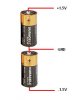
You need two separate power supplies for the transmitter (+5V and -5V), and two more for the receiver.
If ground was connected to nothing, it would not be on the schematic. All the points in the transmitter, and its power supplies, that have the ground symbol must be connected together. All the points in the receiver, and its power supplies, that have the ground symbol must be connected together. The grounds in the transmitter do not have to be connected to the grounds in the receiver. I probably should have drawn the transmitter and the receiver as two separate schematics, to avoid that implication.
You can use two unregulated wall warts for the transmitter, and two more for the receiver, but be aware that, under light loading, the voltage may be higher, so you have to pick op amps that will not be destroyed by the higher voltage.
This place and your guys are the greatest

james
Below are cobbled-up schematics showing the separate circuits with their own power supplies.
 

Attachments

  • cat5 video dvr.GIF
    cat5 video dvr.GIF
    17.9 KB · Views: 207
  • cat5 video rcvr.GIF
    cat5 video rcvr.GIF
    14.6 KB · Views: 189
Last edited:
obrien.james said:
Hi i have a 5v 150ma transformer (wall wart). Can i use this instead of making up the regulated power supply? Am i right in assuming that the +ve 5v on the diagram gets connected to the +ve output and the -ve 5v on the diagram gets connected to the -ve output and the ground is just a common strip on the strip board connected to nothing..

Also if the transformer has a 150ma output how many of these circuit could i run as im thinking of using the smallest number of transforms as possible and just splitting to power to the neccessary circuits.


Also could someone please look through this site which sells op amps as i am not sure which ic i should get, preferably i would like to buy one off of this site but if these are unsuitable please just say so ( **broken link removed** )

James
You can use AD817. They will run on +/-5V to +/-15V.
Why do you need so many channels of video?
 
Last edited:
Basicaly im trying to build one of these https://www.automatedhome.co.uk/article1563.html As they are quite expensive and they are only a circuit i thought that it would be possible to build one myself as i enjoy making things like these and not needing to buy eveything. Thats why i needed so many channels and was confused by the power supply issue as these only have one power in and that is why i thought that i would be able to use just the one.

The circuit on this forum seems to be more involved than the one in the picture in the article above as that sends the composite video as well as the audio (via scart).

if you have any other thoughts on this project please post

james
 
Hi,

Basically im am trying to recreate one of these https://www.automatedhome.co.uk/article1563.html These send composite video + audio (in form of scart cable) over cat5 cabling. this is why i needed to have soo many channels of video as some were going to be used to send audio. It was from that article that i think the confusion over the power supply arouse as it has only one power in hence my previous question about the power!

I wounder if anyone could figure out how the above product works as this is what im basing my project on.

Any thoughts please post


james
 
Status
Not open for further replies.

Latest threads

New Articles From Microcontroller Tips

Back
Top