Continue to Site

Welcome to our site!

Electro Tech is an online community (with over 170,000 members) who enjoy talking about and building electronic circuits, projects and gadgets. To participate you need to register. Registration is free. Click here to register now.

  • Welcome to our site! Electro Tech is an online community (with over 170,000 members) who enjoy talking about and building electronic circuits, projects and gadgets. To participate you need to register. Registration is free. Click here to register now.

Very simple FM experimentation to start with RF

Status
Not open for further replies.

Elerion

Member
I had some free time available this week, so I decided to take a break from my AF projects, and do some RF experimentation.
I've never done anything RF related on my own (appart from a very simple AM receiver, based on a germanium diode), so I found interesting and exciting building a simple FM circuit, and see how it works.

With this one I didn't get a nice sinusoidal oscillations.

Fm-transmitter-Copy.jpg
I needed to replace the 4.7pF with a 10pF, or even higher.
Anyway, even though I managed to get some 90 MHz oscillations, I could hear its signal using an FM radio across a broad frequency range (more than 5 MHz). So it seems to be not very stable.
Then, tried ideas from:

fm_tx2.jpg

The increased base resistor to supply voltage improved things, but the capacitor from emiter to ground just didn't work.
The collector-emitter capacitor has a great impact on frequency, not just the variable capacitor, which has minimal effect. This doesn't make much sense to me.
I'm building the circuit on a small solderless breadboard, using very (very, just minimal) short wires.

If I had to draw some conclusion from my couple of hours experimentation session, I'd say that these simple circuits just can't transmit at a very precise frequency, so they are not really suitable for me.

BUT, there's another thread on the topic:
https://www.electro-tech-online.com/threads/building-a-fm-transmitter.152104/
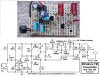
Audioguru posted a circuit he designed. If I look at the second transistor stage, it seems very similar, and I'm sure this one works well...

I'm not interested in good sound quality, and definitely not looking for a complex project, but just some circuit fun to fill spare time. So simplicity is priority. Just a circuit which can transmit a precise frequency (at least, which could not be heard over megahertzs!).
Is this possible, or should I have to go for more complex designs?
 
I'm building the circuit on a small solderless breadboard,
That is likely to be your problem.

A few years ago I did a bit of experimentation with a solderless breadboard compared with soldered ugly construction.
The results are written up in an article here:
https://www.electro-tech-online.com/articles/breadboards-how-bad-are-they-at-rf.278/

I'd say that these simple circuits just can't transmit at a very precise frequency, so they are not really suitable for me.
The simple circuits are susceptible to:
supply voltage variations
stray capacitance variations due to nearby objects
physical disturbance of their components

JimB
 
Anyway, even though I managed to get some 90 MHz oscillations, I could hear its signal using an FM radio across a broad frequency range (more than 5 MHz). So it seems to be not very stable.
Your FM radio is probably cheap and was extremely overloaded by the strong very close-by signal from your FM transmitter. My cheap Sony Walkman FM stereo portable radio has a local-distant switch. On "distant" them my FM transmitter and all local stations are all across its dial but on "local" it is not overloaded but cannot pickup fairly far away stations. My FM transmitter also overloads my cheap clock radio but my hifi stereo radio and car radio are fine with no overloading.

My FM transmitter was a "fix" to a circuit similar to the one you found. It uses a low dropout voltage regulator so that its mic preamp works fine and so that the oscillator radio frequency does not change as the battery voltage runs down.
The frequency changed when something moved towards or away from the antenna since it originally was connected directly to the oscillator so I added the RF amplifier output transistor to isolate the oscillator from capacitance changes at the antenna.
It has pre-emphasis like all FM radio stations have that matches the de-emphasis that all FM radios have then it sounds perfect.

I agree that a solderless breadboard has too much stray capacitance between all the rows of contacts and cannot be used for RF.
 
Yes, sometimes solderless breadboard aren't suitable even for AF circuits, if you are not extreamly careful.
I'll take your advices, and build the circuit on a small board, with proper joints.

Audioguru, I didn't know about "overloading". This could explain.

so I added the RF amplifier output transistor to isolate the oscillator from capacitance changes at the antenna.
So, there're two variable capacitors. How should I tune the RF amplifier's one?

Do you know of any simple reliable FM reciever I could build?
 
I make all my prototypes soldered together on Stripboard. I plan the parts layout so that the board is small and each strip is cut with a drill bit kind of tool so that each strip is used for many parts of the circuit. The strips and a few short jumper wires form a pcb for the parts. I made many very large and complicated stripboard circuits that looked good enough to be sold as the final produce when only one or a few were required. Of course they all worked perfectly.

A good radio has an LC tuned adjustable frequency filter at its input that tunes only the signal frequency that you want. A cheap radio does not tune the input, all the strong local stations (30 of them?) come through the input.
A good radio has AGC (automatic gain control) on its input transistor so that it has a lot of gain for a weak signal but low gain or no gain for a strong local signal. A cheap radio has no AGC so it amplifies all 30 of the strong local signals and becomes overloaded with them so they become all across the dial.

The RF amplifier tuned LC in my FM transmitter has a broad bandpass. I tune it for the most distance at the frequency tuned by the RF oscillator.
A reliable FM receiver is difficult to make and nobody makes them anymore so parts are not available. Years ago Philips made a one IC FM receiver but its performance was poor. Now there are Chinese copies and an entire portable FM radio complete with earphones and a battery is sold at the Dollar store for only one dollar. The dollar pays for the cheap battery (or just the shipping from China) so the battery, radio and headphones are free. I have a few of these FM "radios" that were given away for free at store openings.

Here is my FM transmitter for people to see what we are talking about:
 

Attachments

  • FM tx mod4 pic and schematic.jpg
    FM tx mod4 pic and schematic.jpg
    196 KB · Views: 227
I tune it for the most distance at the frequency tuned by the RF oscillator.

Shouldn't both oscillators be tuned always at the same frequency?
Do you requiere an oscilloscope for doing this?

A reliable FM receiver is difficult to make and nobody makes them anymore so parts are not available.

The whole point for me is experimenting, so if building a FM receiver is not an option, is there any alternative?
Maybe AM instead?
 
Shouldn't both oscillators be tuned always at the same frequency?
Do you requiere an oscilloscope for doing this?
There is only one oscillator to set the radio frequency. The tuned LC circuit at the antenna is on the RF amplifier that isolates the oscillator from capacitance changes at the antenna. This output LC is tuned for the maximum output power (maximum distance).
I am adjusting the output tuning capacitor and on the phone with my wife who is driving away in the car. I say, "Is the signal stronger or is it weaker now?" and keep adjusting it for the strongest output power. My oscilloscope does not go as high as 100MHz.

The whole point for me is experimenting, so if building a FM receiver is not an option, is there any alternative? Maybe AM instead?
AM is very simple and sounds awful. It is simple to create interference with AM but very difficult to create interference with FM. Airplane communications use AM so that an airplane in trouble can break in to another airplane's communications and say, "Mayday, Mayday I am crashing over here because I have run out of fuel!".
There is a crystal radio, a super regenerative radio and a super heterodyne radio in levels of performance and complexity. Since students don't make radios anymore then parts are not sold anymore. Buy a radio, take it apart and make your own radio with its parts.
 
Making my own receiver has two purposes. First is learning, as I said, but the other is being able to work on another frequencies. It is not legal to use regular FM radio frequencies, and I suppose that is so in most countries.

Audioguru, probably most moden cheap radios are encapsulated into custom IC, so it wouldn't be possible to reuse components.

What kind of components are you talking about? Mixers/oscillator 602/612 are still available.

Maybe a silly question, but people into RF electronics are all buying all their equipment? No one builds transmitter/receivers for fun?
 
A radio contains IF transformers and/or crystal filters that are probably not available. The cheap FM radios that I have use a single IC but many capacitors.
Do you want to make a ham radio transmitter and receiver or do you want to make a child's walkie-talkie?

Here is the schematic of the cheap FM radio. All the parts are available but it has two inductors that you might make yourself. Look at all the kits and projects on this website. It has a few language errors so it might be on the other side of the world.
https://electronics-diy.com/fm-radio-receiver-using-tda7088.php
 

Attachments

  • TDA7088 earphone FM radio.png
    TDA7088 earphone FM radio.png
    13.6 KB · Views: 227
Thank you.
Definitely I don't wat to build a ham radio receiver. That is too big of a project for my actual knowledge and available resources. But a child's walkie-talikie sounds nice :D
In short, experimenting with analog electronics, RF related. So I preffer to stay as far as possible from custom ICs, and work with discrete components.

What about this guy?
Works in 3.5, 7 and 14 MHz bands.
The website is in Spanish, so I omit the link, but I look up details if someone is interested.
Esquemaopt.gif
 
Status
Not open for further replies.

Latest threads

New Articles From Microcontroller Tips

Back
Top