Continue to Site

Welcome to our site!

Electro Tech is an online community (with over 170,000 members) who enjoy talking about and building electronic circuits, projects and gadgets. To participate you need to register. Registration is free. Click here to register now.

  • Welcome to our site! Electro Tech is an online community (with over 170,000 members) who enjoy talking about and building electronic circuits, projects and gadgets. To participate you need to register. Registration is free. Click here to register now.

Very old electromagnet advice needed

Status
Not open for further replies.
Hi All

Please see photos!!

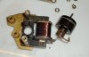
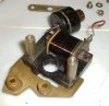
This motor is from an old electric clock what date it comes from I'm not sure but I guess at 20's-30's

I am guessing this is similar to what I know as an electromagnetic motor or synchronous motor??

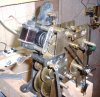
The coil seem to energise the frame which in turn turns the wheels housed in the small circular item with a cog sticking out of it.I am guessing that inside the case is magnets that turn one the coil is energised???

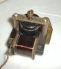
I took the coil covering off (tape) to get to the wires to see if I can get to the end.I can but the wire that forms the coils is hair thin.I think the coils is 11000 ohms as it said this on the covering.

The whole motor runs from 240v AC. One of the wires from the coil is now broken off.

Can someone advise me on how to get it repaired and where. Attaching the two wires from 240v mains to a small unprotected coil scares me somewhat.

Is this coil safe, can it be replaced a by modern equivalent,Can someone or me repair it?

Would be grateful of help with this one as it's an important clock that need bringing back to life.

Cheers
 

Attachments

  • Img_0020..jpg
    Img_0020..jpg
    36.8 KB · Views: 1,022
  • Img_0021..jpg
    Img_0021..jpg
    43.8 KB · Views: 750
  • Img_0019..jpg
    Img_0019..jpg
    38.2 KB · Views: 702
  • Img_0013..jpg
    Img_0013..jpg
    118.5 KB · Views: 749
Last edited:
I click on your web page link and it says "403 Forbidden You don't have permission to access / on this server."
 
You haven't attached the pictures and I'm forbidden to look at your page!

Mike.
 
Hi Mike

The motor seems to be a continuous wind motor as there is no function to switch it off.There is a manual wind option also.

The round unit with the cog. on it also says ' TOR. mm 50'

hi Mark,
If the broken thin wire is on the outside of the coil, taking off a couple of turns , so that you can reconnect, will be OK.

Eric
 
I'd get one of the old style solder terminals like this, **broken link removed** epoxy it to the side and then solder the fine wire to it. If you cut a strip of 3 and remove the two outer ones you have a nice surface to glue to.

Mike.
 
Ignoring the effects of inductance etc (which make a big difference), you can use ohms law to get a very rough approximation.

240v / 11000 ohms = 22mA (so 5W)

That's not going to explode - might get a bit hot dissipating 5W. However, in reality, the current will be MUCH lower, as it is a coil.

I'd be happy connecting that to 240v.

A
 
Last edited:
Hi
On further inspection of the coil both wire are now broken, frame of the coils was just too unstable to examine.I now have no choice but repair.

I could unwind the coil and rewind on another frame or get a company to do this for me.
Any advice here would be good.

Regards
 
I'm not sure what you are saying the problem is.

Can you not just unwind a few turns from each end, and solder on new wires? Prehaps glue the larger wires to the frame before soldering to provide strain relief.
 
Hi
On further inspection of the coil both wire are now broken, frame of the coils was just too unstable to examine.I now have no choice but repair.

I could unwind the coil and rewind on another frame or get a company to do this for me.
Any advice here would be good.

Regards

hi Mark,
The enamel covering on the old wire will be dried out and brittle, if you unwind and rewind.

Unwind the coil, count the turns and note the winding direction.

Get some new enamelled wire of the same gauge.

Make a mandrel using a bolt and two pieces of plastic.

Fix the bobbin on the mandrel, place the mandrel in a handrill chuck, clamp the drill in a bench vice.
Wind on the same number of turns in the same direction.

You must fill each layer of turns if you have a hope of getting the same number of turns on the bobbin,,, dont pile wind.

Being mains, I would add a little extra insulation on the lead out wire from inner layer.

Good Luck.!;)
 
Last edited:
I'm not sure what you are saying the problem is.

Can you not just unwind a few turns from each end, and solder on new wires? Prehaps glue the larger wires to the frame before soldering to provide strain relief.

Hi
The problem is now that the wire that's deep inside as also broke so no choice to replace or attempt to make one myself.I's a very old unit and can't hardly touch it before it brakes

Regards
 
hi Mark,
The enamel covering on the old wire will be dried out and brittle, if you unwind and rewind.

Unwind the coil, count the turns and note the winding direction.

Get some new enamelled wire of the same gauge.

Make a mandrel using a bolt and two pieces of plastic.

Fix the bobbin on the mandrel, place the mandrel in a handrill chuck, clamp the drill in a bench vice.
Wind on the same number of turns in the same direction.

You must fill each layer of turns if you have a hope of getting the same number of turns on the bobbin,,, dont pile wind.

Being mains, I would add a little extra insulation on the lead out wire from inner layer.

Good Luck.!;)

Hi Eric
Not sure I will come up with good results so might be better off getting an expert to do it. You know of one?

Regards Mark
 
You could try a local transformer or motor winding company?

Motors this size aren't normally worth repairing, although this clock might be worth a lot.

How about getting it valued?

Then you can decide whether to repair the motor or replace it with a more modern equivalent.
 
This is a compete guess, but you might have some luck with finding a solenoid or relay coil that would fit. The frequency is the important part (fixed if powered from mains) - the only thing the number of windings will affect is the strength of the magnetic field and thus the strength of the motor.
 
This is a compete guess, but you might have some luck with finding a solenoid or relay coil that would fit. The frequency is the important part (fixed if powered from mains) - the only thing the number of windings will affect is the strength of the magnetic field and thus the strength of the motor.


Hi
Think this is one for the pro's but the info on the coil is 11000 and on the small electromag motor - 'tor 50 mm' I would gues this is something to do with Torque.

Thanks for the advice.
 
You could try a local transformer or motor winding company?

Motors this size aren't normally worth repairing, although this clock might be worth a lot.

How about getting it valued?

Then you can decide whether to repair the motor or replace it with a more modern equivalent.

Hi Hereo

I might end up looking through the yellow pages or the net for someone to take it on.The clock is deffo worth the effort, very rare early model of a National Electric wall clockl.

It's not a big emergancy as the clock also has manual wind where I suppose is used in times of power cut.Would like to get it back running on the motor.

Regards
 
Last edited:
You could get a newer analog clock that is mains powered and see if the motor from that could be adapted. I don't know much about the area you live ,but here in the US we have Thrift Stores, Salvation Army Stores and flea markets. Clocks with motors like this a quite common.

Most companies didn't make their own motors for some thing like this, so any number of brands use a similar motor. And they are similar dimension wise between manufacturers.
 
Status
Not open for further replies.

Latest threads

Back
Top