Continue to Site

Welcome to our site!

Electro Tech is an online community (with over 170,000 members) who enjoy talking about and building electronic circuits, projects and gadgets. To participate you need to register. Registration is free. Click here to register now.

  • Welcome to our site! Electro Tech is an online community (with over 170,000 members) who enjoy talking about and building electronic circuits, projects and gadgets. To participate you need to register. Registration is free. Click here to register now.

Very Loud Buzzer Circuit

Status
Not open for further replies.

ckeays

New Member
Hello, I hope everyone is well.

I created a bicycle horn from a CO detector simply because the buzzer is
extremely loud and can be heard from a long distance.

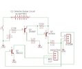
When I use the (modified) CO detector board the buzzer is very loud.

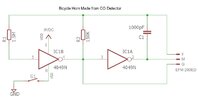
I created my own circuit from a schematic I found on the net,
however the buzzer is not as loud as it was on the original board.
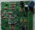
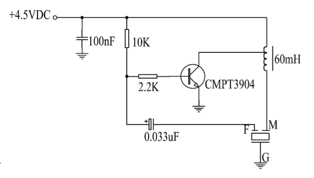
I have included my circuit below.

Any advice as to how I can increase the volume on the buzzer?
For the R1 resistor, I used 1M instead of 1.5M because that is all I had here.
Any advice is greatly appreciated.
 

Attachments

  • Horn.jpg
    Horn.jpg
    71.6 KB · Views: 465
Last edited:
In your circuit, R1 is there to prevent the IC1B input stage protection diodes from messing up the oscillator waveform. As long as its value is 10x R2, just about anything will work.

If the sounder is a 3-terminal piezo element, then the original circuit might be driving it at its self-resonant frequency. This is the way to get the max possible volume despite minor variations in the elements due to production tolerances.

Another possibility is that the 4049 cannot source or sink very much current, maybe much less than the original circuit components.

Photos of the original circuit board?

ak

ps. Gold star for having reference designators.
 
Last edited:
Here are two variations. One is a CMOS circuit with paralleled inverters to increase drive current, and one is a 1-transistor version. Note that the transistor can move a lot more current than a single inverter output stage.

ak

Piezo-Beeper-201319203339342.jpg


FESB4ICHR4ST0A9.LARGE.gif
 
Wire up the other 4 inverters in your original circuit in parallel with IC1A.

Highly recommend you looking at 4049 pins in terms of voltage outside its Vdd and VSS
pin or clamped to that pin + a diode drop. If you see that add external diodes at pin to
ground (especially 4049 inputs, for protection) -


1632171261797.png


I am thinking IC1B input is potential problem pin, rupturing its gate oxide input
due to excessive transient V.


Regards, Dana.
 
Last edited:
Photos of the original circuit board?
Not a very good one but here it is. This is the CO detector board. It worked well for 4 years until recently.
It is necessary for the horn to be very loud so I can warn others that are far away that I will be passing them
(just in case they decide to move in front of me at the last second). This horn has saved me many times.

I haven't found any bicycle horn (reasonably priced) that is as loud as the CO detector buzzer!
 

Attachments

  • CO_Det.JPG
    CO_Det.JPG
    1.5 MB · Views: 250
Last edited:
I am thinking IC1B input is potential problem pin, rupturing its gate oxide input
due to excessive transient V.
Nope. That is what R1 prevents. It also prevents soft-clipping of the capacitor voltage waveform, which would increase the oscillator frequency above the calculated value.

ak
 
What is a CO2 detector? We breath out CO2 and soda pop has CO2 in it, it is not dangerous.. Maybe it is a CO detector because CO is poisonous.

A CO detector circuit uses a transducer is a piezo that is loudest at 3kHz to 5kHz. Its frequency is much higher than then 455Hz of your CD4049 circuit.
I agree that its piezo uses 3 wires (one wire is for feedback) so that it operates at its loudest frequency.
 
Nope. That is what R1 prevents. It also prevents soft-clipping of the capacitor voltage waveform, which would increase the oscillator frequency above the calculated value.

ak
Agreed, did not look at left hand side of schematic. No one trained me to look at the whole
schematic :)
 
Often an inductor is used to increase the drive voltage (and hence volume). Your photo of the PCB seems to show a blue inductor in the top right corner?
Here's a driver circuit for your transducer, incorporating a tapped inductor (unknown tapping point): http://www.east-elec.com/sounder/efm-290edfp
EFM-290EDFP-circ.png

Another driver, this time with an untapped inductor: http://ki3u.byethost3.com/Instruments_etc/Exp_Gas_Detector/Exp_gas-detector-alarm.html
View attachment 133793
I have all of the other components except the inductor.
I do have one of these:
Inductor

Would this work on the circuits you posted? The inductor I have is 5.6uH (0.0056mH).
 
Is there any way I can increase the frequency in my circuit in post #1 above?
Like maybe change the capacitor?
 
Would this work on the circuits you posted? The inductor I have is 5.6uH (0.0056mH).
Based on the linked circuits, that's 3000x too small, so I don't think you'll have much luck.
Your 4049 IC has unused inverters; have you tried paralleling them, as per AnalogKid's post, above? This should give you some increase in volume with the parts you have.
Is there any way I can increase the frequency in my circuit in post #1 above?
Like maybe change the capacitor?
Why do you want to increase the frequency? The circuit should oscillate at the resonant frequency of the transducer, thus max output. The 455Hz mentioned by audioguru will just be to kickstart the transducer initially.
 
I wired up the CD4049 inverter using all of the inverters like in post #4 above (thanks AnalogKid).
It is very loud but still not as loud as the alarm board (using the same buzzer and voltage)

I tested both circuits (by ear) side by side and the alarm board is definitely louder.
The 4049 version is loud enough, however I am just curious as to why it is louder.

I created a schematic of the actual buzzer circuit on the CO board. I triple checked it.
I am hoping it is correct. If something is obviously wrong please let me know.
I am not very experienced with eagle.

I didn't find a 3 pin inductor so i just used a 3 pin header and labeled the pins, same with the buzzer.

I also don't know what part number the inductor is,
as there are no markings on the component except for one red dot.
(you can see the component I am referring to in post # 7, the blue component in the picture)
Hopefully someone will know what the value is so I can order a few of them.
 

Attachments

  • CO_Buzzer_Circuit.jpg
    CO_Buzzer_Circuit.jpg
    114.2 KB · Views: 386
Most of those parts just make up a switch. The oscillator part only uses a single transistor. Here it is without the unneeded parts:
simplified.jpg

The circuit is similar to the two I posted, above. You can make your own 3-legged inductor by winding a bunch of turns around a 2-legged inductor (you want 10mH or above). Alternately, just use the circuit that doesn't need the 3-legged inductor.
 
I tested both circuits (by ear) side by side and the alarm board is definitely louder.
The 4049 version is loud enough, however I am just curious as to why it is louder.
With a 9V supply, the 4049 circuit can drive the piezo with 9V one direction, and 9V in the other; this is 18V peak-to-peak (maximum; limited by 4049 output current). The circuit with an inductor will drive it 9V in one direction, and spikes of perhaps up to 50V (wild guess), in the other direction. You'd expect this to make it louder.
 
Status
Not open for further replies.

Latest threads

New Articles From Microcontroller Tips

Back
Top