Continue to Site

Welcome to our site!

Electro Tech is an online community (with over 170,000 members) who enjoy talking about and building electronic circuits, projects and gadgets. To participate you need to register. Registration is free. Click here to register now.

  • Welcome to our site! Electro Tech is an online community (with over 170,000 members) who enjoy talking about and building electronic circuits, projects and gadgets. To participate you need to register. Registration is free. Click here to register now.

vector concepts of divergence, curl and gradient

Status
Not open for further replies.

PG1995

Active Member
Hi

These days I'm learning about vector concepts of divergence, curl and gradient on a basic level.

Q1:
I was reading this Wikipedia article on the curl where it was written:

Intuitive interpretation

Suppose the vector field describes the velocity field of a fluid flow (such as a large tank of liquid or gas) and a small ball is located within the fluid or gas (the centre of the ball being fixed at a certain point). If the ball has a rough surface, the fluid flowing past it will make it rotate. The rotation axis (oriented according to the right hand rule) points in the direction of the curl of the field at the centre of the ball, and the angular speed of the rotation is half the magnitude of the curl at this point.

As the article says:

In vector calculus, the curl is a vector operator that describes the infinitesimal rotation of a 3-dimensional vector field. At every point in the field, the curl of that field is represented by a vector. The attributes of this vector (length and direction) characterize the rotation at that point.

The curl gives us a direction of rotation and length/magnitude of that vector of rotation. What does the line in red mean in the quoted text above? Please help me with it. Thank you.

Q2:
Another article I was reading says:

In vector calculus, divergence is a vector operator that measures the magnitude of a vector field's source or sink at a given point, in terms of a signed scalar. More technically, the divergence represents the volume density of the outward flux of a vector field from an infinitesimal volume around a given point.

I was thinking that in case of electric field the divergence is equivalent to magnitude of flux density. The magnitude of flux density is given as:
flux_density-jpg.73884


But I think I was wrong. Divergence = Flux/volume. The divergence is flux per unit volume but flux density is flux passing per unit area. What do you say? Please let me know. Thanks.

Regards
PG
 

Attachments

  • flux_density.jpg
    flux_density.jpg
    3.9 KB · Views: 677
Last edited:
Hi there,


The angular speed is just the speed in rads/second around the point of rotation. That's a measure of the tendency for a vector field to rotate about a fixed point.

Just a quick note about the calculation of the curl...
The curl is often represented by the notation used for a determinant (this is all one determinant but doesnt draw correctly):

[LATEX]
\left| {\ \textbf i \ \ \ \ \ \textbf j \ \ \ \textbf k \ } \right|
[/LATEX]
[LATEX]
\left| \frac{\partial}{dx}\ \ \frac{\partial}{dy} \ \ \frac{\partial}{dz} \right|
[/LATEX]
[LATEX]
\left| \ f \ \ \ \ g \ \ \ h \ \right|
[/LATEX]

but we have to be careful to remember that to expand a determinate by the dimension-1 sub matrixes the component in the direction of j gets multiplied by -1 as:


[LATEX]+\ \left| \ \ \ \right|\textbf i \ \ \ \ -\ \left| \ \ \ \right|\textbf j \ \ \ \ +\left| \ \ \ \right|\textbf k [/LATEX]


where each sub matrix is indicated by the two vertical lines (without showing contents for simplicity). The main thing here is that the center component is negative. In the formula often shown where all the partials are drawn out explicitly the "center" sign is shown as positive, but that's because they swap the signs inside the parentheses so the results come out the same, but it is a little confusing sometimes. It's also not really correct to draw the 'j' as '-j' because then that implies that we have to calculate a determinant where we make the 'j' term negative, and then have to negate that again and this would create the incorrect result for the curl along 'j'. I've seen it drawn with the negative sign on the web so i thought i would mention this. If they draw the sign we have to be careful not to negate the center term twice and end up with a positive value for that component :)

This can be proved by looking at the field:

F(x,y,z)=yi-xj+0k

and determining the direction of the curl, then comparing that to:

F(x,y,z)=zi+0j-xk

which is the very same field except it is now in the x,z plane instead of the x,y plane. The curl for this second field has to come out positive (while the first has to come out negative) because this new field is the same as the old field if we rotated the coordinate space 90 degrees along the x axis. For the old if z is pointing out of the page and y up and x to the right, after rotation the z would be pointing up and x still to the right but now the y axis would be pointing into the page which means the curl along y with the second field has to be opposite to the curl along z with the first field.

If we placed a little sphere in the field and noted the rotation, that would indicate the curl. For two dimensions, we can use a small wheel where the wheel is forced to rotate by the field if there is a rotation in the field at that point. For example if the vector above the wheel is larger than the vector under the wheel the wheel would tend to rotate in the direction (top part) of the top vector (so the bottom of course moves the other way). If the vectors were equal (and in the same direction) we would not see a rotation because the two would push on the bottom of the wheel and the top of the wheel by the same amount so the two pushes would cancel out.


The divergence is a measure of the rate of change of how much material is moving outward from a point. If there is constant flow then there is zero divergence. If the flow is out from a closed surface then the divergence is positive, if it is inward then it is negative.
Here's a video that i think might help...

https://www.youtube.com/watch?v=Stg6wwlbTws&feature=endscreen&NR=1


I took some time to draw some diagrams of a vector field and show some properties like this but it's very hard to draw vector fields in 3d on a static 2d drawing surface, especially when we have rotations and stuff because it's hard to tell what the arrows are actually pointing to :)
 
Last edited:
Thank you, MrAl.

In **broken link removed** video the presenter calculates the divergence to be 1/2 or 0.5. To me, this means that the divergence is positive but the velocity of particles going to the right is decreasing. But check out the vector field drawn in the view, it shows that the velocity of the particles increases as they move to the right. In my view, if the divergence were, say 2, then this would mean that the velocity of the particles gets increased by factor of '2' as they move to the right. Do I have it right? Please let me know. Thank you.

Regards
PG
 
Last edited:
Hi again,


Here are a few graphs you can look at. The vector length is shown in black at the tip of the vector, the divergence is shown in green near the center of the vector and the center of the vector shows the point that the vector is representing.

It got a little more difficult to draw that fourth vector field so i started to modify my slope field plotter program to be able to handle vectors. Im still working on it but a plot of a similar field is shown in the little window labeled "Plot". The vector tips are shown in red, tails in black, with the center of the vector being the point that the vector represents.

First check them over to make sure they are all right (at least the first three) and then see what you think about your idea and these four vector fields.

Note that i was drawing the vector field with each 'arrow' centered on the point, but often they are drawn with the tail of the 'arrow' at the point and the vector body all to one side of the point (or above or below the point as needed).
 

Attachments

  • Div-01.gif
    0 bytes · Views: 2
  • Div-01b.gif
    Div-01b.gif
    67.2 KB · Views: 341
Last edited:
Thank you, MrAl.

Please check the attachment. I hope I have it right and even if I still have it 'little' wrong then I believe it's okay for the time being! I can improve my understanding as I go along learning more of this stuff. Thanks.

Regards
PG
 

Attachments

  • divergence333.jpg
    divergence333.jpg
    123.5 KB · Views: 366
Last edited:
Hi,

Yes, that's true in one dimension but only for a one dimensional problem.

The reason i provided so many plots was so that you could compare the first two with the other two.

When we look at the "Div" shorthand notation we see the grad being dotted with the vector function. But it's not really the grad it's just the symbolism of the grad and it shows that if we use a similar operation with those partial derivative symbols of the grad with the function we get the Div. So the Div is a short of dot product of the function with the symbolic grad. But the dot product makes a single quantity, so we get a single number that represents something about the entire 3d field or 2d field (or higher). Think about that. A single number that represents something about 3 different directions.

Now the grad is almost the same thing, except that provides us with three different numbers, one for each dimension. That tells us something about each dimension independently. But the Div is the sum of these components.
For example, say we have the function F=Axi+Byj+Czk.
The grad is:
<A,B,C> a vector
(and note that A tells us about the change in x along i).
But the Div is one number only:
A+B+C

So we already have something that tells us the change in x along x (the grad) and so the Div is a little different, the Div is the sum of all the partials.

We'll have to look at this some more at some point. Im still working on my grapher to graph the vector functions and that might help to see some details about these fields.
 
SOME INSIGHT INTO THE DIVERGENCE


See the attachment while reading this post.
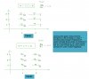

Fig 1:
The flow field equation F, the div calculated, the flow field drawn with small arrows
where the small red points are the tips of the arrows representing the vectors.
Note the vectors are drawn as 1/2 of their actual length to make the drawing more clear.

Fig 2:
The field drawn a little better but only along the diagonal in the first quadrant.
Vector lengths drawn here reflect their actual length.

Fig 3:
A circle of radius r drawn with the same scale not showing the field, but instead
showing the outward unit normals from the circle (green). The outward normals have direction.

Fig 4:
The circle and outward normals with the field (along the diagonal) drawn. It is
observed that the field does not always point in the same direction as the
outward normals. Some point in the same direction (upper right) and some point
opposite to it (lower left).

Fig 5:
Since Fig 4 doesnt show all the field vectors, it should be clear that the vectors
cross the border of the circle all around the circle not just along the diagonal.
Thus, they cross sometimes in the same direction, sometimes opposite, and
sometimes perpendicular, and sometimes at various other angles to the normals.

Fig 6:
Same diagram with the outward normals removed for clarity. The lengths of two
of the vectors along the diagonal are marked L1 and L2, with L2 being the longer
one. L2 is always the one leaving, L1 always the one entering.

Fig 7:
Same diagram except now we see the circle drawn smaller. The circle is smaller so
the area is less than in figure 6. Note also that the vector leaving the circle
now is smaller than the one leaving in figure 6. So the difference in length of
L2 and L1 has gotten smaller as well as the area of the circle.

Fig 8.
The circle is even smaller now, and thus would have a smaller vector coming out of
it's upper right side, so the difference in length between the large vector
(had it been drawn here) and the small vector will be even less than before, and
also the area of the circle has surely decreased.


Now for the math that ties all these together...


The flux f1 from the small vector with length L1 is simply the length of the vector.
However, since there are many vectors entering the circle on that side we need a way
to account for all of those vectors without having to calculate each and every one
(which we could do if we wanted to take that much time and rigor). So to make it
a bit simpler to calculate, we note that if all of the vectors were at the same angle
they would all enter at the same angle, and the ones leaving would also leave at the
same angle. But also, some of the ones entering will not be in line with the normals
but then an equal number leaving would also not be in line but would be at the same
angle except their direction is outward instead of inward. So to keep this simple
we make the flux entering the circle equal to half the circumference of the circle
(half because that's the only border that is crossed by those influxes) times the
length of that one flux vector:
Fin=2*r*pi/2*L1=r*pi*L1
and following the same logic we do the same for the outgoing vectors:
Fout=r*pi*L2
except of course that we multiply by that one outgoing vector L2.

Ok, so the flux in is Fin and the flux out is Fout, so the total flux
leaving the circle is:
Ftotal=Fout-Fin

Now the area of the circle is:
A=pi*r^2

and the Div is the net total flux divided by the area (in 3 dimensions it would be the flux/volume):
Div=Ftotal/A

So to calculate the Div we calculate the lengths of the two vectors L2 and L1 from
the flow field equation:
F = 0.2*x i + 0.2*y j

at the two points x1,y1, and x2,y2, multiply by half the circumference, take the difference,
then calculate the total area of the circle, then divide.

So lets start with the bigger circle.

For the big circle we have points:
x1=1, y1=1, and
x2=3, y2=3

Now we do point 1 first:
Fx(x1,y1)=0.2
Fy(x1,y1)=0.2

and L1 is just the norm:
L1=sqrt(0.2^2+0.2^2)=0.2828 approximately

And now for point 2:
Fx(x2,y2)=0.6
Fy(x2,y2)=0.6

and L2 is just the norm:
L2=sqrt(0.6^2+0.6^2)=0.8485 approximately

The circle diameter is:
dia=sqrt((y2-y1)^2+(x2-x1)^2)=2.828 approximately

and so half the circumference is:
C2=dia*pi/2=4.442 approximately

so the estimated total flux entering is:
Fin=L1*C2=1.256

so the estimated total flux leaving is:
Fout=L2*C2=3.769

Note we have quite a bit more leaving than entering.
The total flux across the border of the circle is:
Ftotal=Fout-Fin=3.769-1.256=2.513

The circle radius is half the diameter:
r=dia/2=1.414

so the area is:
A=6.281 approximately

so the Div is:
Div=Ftotal/A=2.513/6.281=0.4000955 approximately.

The Div calculated from the standard way to calculate it is 0.4 so this is our first approximation.
We did get a little lucky here though in that our first approximation came out so close. This
most likely will not happen with more complex fields so we'd have to decrease the circle size
and look at the smaller vectors to get a better approximation.
Also keep in mind that we really should have calculated more crossing vectors and summed
the results. Maybe next time :)


[LATER]

The numbers look accurate (at least accurate enough) so i guess there is nothing more to do. We could let the circle becomes smaller and smaller, but since we've already got the right number it seems a waste of time to do that with this example. What should happen with most fields is as the circle gets smaller and smaller we should see the Div calculated this 'long' way match closer and closer to the Div calculated in the normal way.

Just one small note about the sign of Div...
When the Div is calculated the sum of vectors leaving the circle was larger than those entering the circle, so the result was positive. If the sum of vectors leaving is smaller than the sum entering then the result will be negative (L2 is the length of the vector leaving and L1 is the length of the vector entering, and since L2>L1 then L2-L1 is positive, but if the vector leaving (L2) is smaller than the one entering (L1), then of course L2-L1 will have to be negative).

In three dimensions we could not use a circle but instead would have to use a sphere. While the circle can 'sense' direction in any plane angle, the sphere unit normals are omnidirectional in all three dimensions so it can 'sense' direction from any solid angle. Here we would have the 3d vectors crossing the surface of the sphere instead of the border of a circle, and the inside of the sphere is a 3d volume not an area. To get the Div we could use smaller and smaller spheres and as the spheres get smaller and smaller the approximation would get closer and closer to the actual Div in three dimensions.

Just one additional small note about the drawing of the circles as they get smaller and smaller...
The circles drawn in the diagram near the bottom get smaller and as they do it is clear to see that the vectors crossing the border of the circles get smaller as the circle gets smaller, but in those drawings we allowed the center of the circle to move along the diagonal when really we would not do that. We would instead keep the smaller circles centered around the same x,y point as the larger circle so only the diameter would change, not the location. The circles drawn however do show the same thing as far as the vector lengths are concerned, in that they do get shorter as the circle gets smaller. Drawing the circles all centered at the same point allows us to state that the divergence at that one point is what we calculated. For this field the Div is the same at any point, but for other vector fields this very well may not be the case so it is better to think of the circles as being all drawn at the same center point no matter what their radius is. I could update the drawing but it would be harder to see the vectors getting smaller, and it's not too hard to imagine the circle getting smaller but staying centered at the same point as the larger circle.
 

Attachments

  • Div-02.gif
    Div-02.gif
    71 KB · Views: 353
Last edited:
Status
Not open for further replies.

Latest threads

New Articles From Microcontroller Tips

Back
Top