Continue to Site

Welcome to our site!

Electro Tech is an online community (with over 170,000 members) who enjoy talking about and building electronic circuits, projects and gadgets. To participate you need to register. Registration is free. Click here to register now.

  • Welcome to our site! Electro Tech is an online community (with over 170,000 members) who enjoy talking about and building electronic circuits, projects and gadgets. To participate you need to register. Registration is free. Click here to register now.

variable voltage power supply

Status
Not open for further replies.

mahmoud shendy

New Member
Hi all
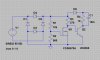
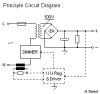
i want to design variable voltage dc power suply from 0 to 140 Vdc with current up to 8A..
how can i do that circuit? is it difficult or easy?
i read about SMPS and Buck converters but i did n't know how to do my task..


thanx in advance ... Shendy
 
What's the input voltage?

This isn't easy.

Does it need to be regulated?

I would use a 100V transformer with a variac on the input and a bridge rectifier and huge capacitor on the output.
 
dear hero, the input voltage is 110Vac. by the way i do not want to use a variac , there is not a room to make this and also it will be heavy..
i say to you that the first think of me is to recify the 110Vac and then smoothing it by large cap bank ,then a chopper circuit will copping the dc by a certain duty cycle, now i don't know how to make this chopper circuit..
thanx again
 
You're talking a very high power, complicated and expensive system, which during development is likely to go 'poof' a lot and kill lots of expensive components.

This is seriously not trivial, what's it for?.
 
This is an old and simple idea that is mainly used in dimmers. I tried a simulation in a LTspice and it looks feasible. Only 60V input was simulated because I don't have a model of better transistor.

The R1/R2 control when the M1 turns on/off and thus an output voltage. As can be seen from I(R4), the output is DC at 0.7A (i.e. approx 7V output).

The values are for simulation only, make your own proper design.
 

Attachments

  • ac2dc.zip
    738 bytes · Views: 179
  • ac2dc-1.jpg
    ac2dc-1.jpg
    40.5 KB · Views: 417
  • ac2dc-2.jpg
    ac2dc-2.jpg
    96.6 KB · Views: 259
Last edited:
uhhhh, not quite the kilowatt that the OP asked for....looks to me more like ten watts.

It was just a proof of concept, not a design. I do not have models of powerful enough parts readily available in my spice software.
 
Dear All.. thanx for your help and interest of my question..
all i need is to drive a coil of impedance about (20 Ohm) by a current of about (6A)
how to do so if the thinking of SMPS is hard and difficult..
thanx again for help and interest...
 
0-140V DC Principle Circuit Diagram

A difference Circuit Blok Diagram.
 

Attachments

  • variable voltage power supply sorusuna Dimmer ile önerim.png
    variable voltage power supply sorusuna Dimmer ile önerim.png
    4.2 KB · Views: 905
Status
Not open for further replies.

Latest threads

Back
Top