Continue to Site

Welcome to our site!

Electro Tech is an online community (with over 170,000 members) who enjoy talking about and building electronic circuits, projects and gadgets. To participate you need to register. Registration is free. Click here to register now.

  • Welcome to our site! Electro Tech is an online community (with over 170,000 members) who enjoy talking about and building electronic circuits, projects and gadgets. To participate you need to register. Registration is free. Click here to register now.

Variable Frequency Input - Proportional PWM Output

Status
Not open for further replies.

BlakeM

New Member
Hello,
I am new here & also to Arduino.

Is it possible with Arduino to have a variable frequency (Pulsed) Input to create a proportional PWM Output?
I know you can have a variable analogue voltage Input to create a proportional PWM Output but I am not sure about doing this with a variable pulsed frequency Input?

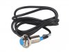
My frequency input is from a Hall Sensor & the Frequency operating range is from 0 Hz to 1 kHz but this can be adjusted to suit.

If this is possible could someone point me in the right direction please.

Thanks
 
Welcome to ETO, BlakeM!

Yes. At its simplest, sampling the time between the first few input pulses will give you a number that you can massage (if necessary) to then control the PW of your output signal.

A little more code and you can constantly monitor the input timing (frequency).

There will be, of course, a minuscule delay between the sampling and the corresponding PW change.

You can incorporate machine code (uC timer control, necessary for what you're suggesting for any reasonably real-time response times) within the "normal" (C++ like) coding for the Arduino.
 
Last edited:
Thank You for the very fast response.

Ok, If I sample the time period as you say between the pulses, do I then Map that to a PWM output?
Not sure where to start with this, do you know of any such examples or reading on the net I could have a look at?

Thanks
 
Ok, If I sample the time period as you say between the pulses, do I then Map that to a PWM output?
Yes. Another way to say this is to assign a variable to that value and then later in the code use that variable to adjust the PW.

The Arduino world is rife with code examples. I've always told new users to just bang away with the simple stuff out there, since the learning curve (at least for me) was more clogged up with syntax errors (code construction errors :banghead: ) than it was with my basic ideas.
 
Ok, I will have a go, I have a few idea's that I will try.

Yes, I like to learn by doing rather than taking the easy way out.

I will post an example sketch when I have it done.

Thanks for the replies & suggestions.
 
Hi,
Yesterday I started writing some code in an over elaborate manner until total confusion set in & I then realised that the seemingly complex issue at hand was quite simple with different thinking.

So I now have a huge amount of code to do a very simple task, I have attached the code.:)
It appears to work very well.

At the moment I have a 555 timer supplying the variable frequency into the Arduino & when I remove the positive power to the 555 I still have approx a 80mV pwm signal out of the Arduino & not Zero output as expected?
Any hints on fixing this issue?

Code:
int pin = 7;
int PWM = 5;
unsigned long duration;

void setup(){
  pinMode(pin, INPUT);
  pinMode(PWM, OUTPUT);
  Serial.begin(9600);
}

void loop(){
  duration = pulseIn(pin, HIGH);
  int val = digitalRead(7);
  val = map(duration,750,37000, 255,0);
  analogWrite(5,val);
  }
 
Last edited:
Do you have a pulldown resistor (or some other 10k or higher load) on pin 5 when you're testing the output level with the 555 de-powered?
 
Last edited:
Yes,
I had a 10K load resistor on the Output & have just now tried a 4.7K & the Output still is around 55mV ?
Not sure why?

Thanks
 
Forgot to ask what the 80mV (now 55mV) signal looked like (pulse, steady state DC... etc).

You might need to put in a constrain() after the map function, i.e., last "duration" value when you shut down the 555 still hanging around.
 
Yes, it is a pulse of around 500Hz which I think is the std PWM frequency of the Board which is I believe to be 490Hz?

I tried disconnecting all external circuits & ground wires etc & it seems that the pulse is coming from the Arduino Board.
I then tried disconnecting the USB cable & used a battery to supply power to the Arduino just in case but the pulse is still there?

It appears to be the PWM frequency of the Board?

I'll try as you suggested, not sure how to do that yet but I will look into it?

Thanks
 
I tried the "Constrain" method but it still didn't fix the issue so I tried a different attack to turn OFF the PWM & it works great:
////////////////////////
if (val < 10)
{
digitalWrite(5,LOW);
}
/////////////////////////
Thanks for helping me with this & it was only due to your comments throughout this thread that I was headed in the right direction to get the whole sketch working & it got me thinking, which is hard at best.
I appreciate the help greatly!
Thank You!
 
Again, you're welcome, BlakeM.

And thank you for helping keep my brain engaged... :woot:.
 
Hi cowboybob,
I need to map the Output to the Input so it is proportional to the pulsed Input.
Basically I require a Linear 0V to 5V Output.

I thought this would be the easy part :confused:?
I lack the understanding of how to work this out correctly, I tried several "guesstimates" but this requires more than a shot in the dark approach & I am unsure exactly how to achieve this?

I can adjust the Hall Sensor Frequency Input to suit what works out the best say 0 Hz to 300Hz or 0 Hz to 600 Hz or whatever is required or more suitable to achieve a Linear Output.
How do I go about mapping this correctly?

Thanks
 
Just thinking more about this, I am not sure I have my sketch correct for the Hall Sensor?
With the "pulseIn" function I am reading High to Low so I am reading the On time of the pulse.
If I am correct I think the Hall Sensor will have a pulse of equal On time no matter what the frequency is?

So I have to read from Low to High & read the varying Off time, do I have this correct?
No. Frequency is most generally determined by measuring the time from one rising edge to the next. (Using the descending edges is also possible, of course, - oscilloscopes have that feature as part of the "Triggering" options).

I am assuming that the Hall effect is being triggered by a rotating magnet. Thus the pulse width AND frequency will change with varying RPM: Low RPM = longer pulse width AND lower frequency, with the opposite being true as RPM increases.

I am also assuming that, with a single Hall device, the time between pulses will almost invariably be significantly greater that the timing of the pulse itself.

So, the obvious signal of choice for a reasonable control number for the "W" of PWM output would be the pulse width (High to Low) number to allow for this data to control a subsequent PWM pulse from the Arduino.

If you want the Arduino output pulse width to increase with an increasing RPM of the triggering magnet, you'll need to reverse the order of your mapping conversion from high to low.

And, of course, the PWM duration will remain stable between Hall triggers.

Here's an interesting alternative: https://www.pjrc.com/teensy/td_libs_FreqMeasure.html (it measures
 
Ah, I see!
Yes, the Hall device will be triggered by a magnet inserted into a hub on a shaft.
I should have been more specific about the Hall device it is a " NJK-5002C Hall Sensor Proximity Switch NPN 3 Wire. "
I cannot find a Datasheet on this being Chinese?
I have attached a picture of it.

The Frequency Measure sketch is nice, thanks for the link, this is very helpful.
I will try to get things working using this sketch as it does seem to simplify trying to map things correctly---well maybe:)

Thanks
 

Attachments

  • NJK-5002C Hall Sensor Proximity Switch NPN 3 Wire.jpg
    NJK-5002C Hall Sensor Proximity Switch NPN 3 Wire.jpg
    25.7 KB · Views: 285
I modified the Sketch you mentioned & now it all works very nice.
I have attached a Graph of the Frequency (Hz) vs the PWM Output & it is very close to being linear, beautiful.
I did the quick test from 50Hz to 300 Hz with 25 Hz increments.

This was much easier to map correctly:D

Once again Thank You!
I am right to go with this now!

Thanks
 

Attachments

  • Frequency Vs PWM Output.PNG
    Frequency Vs PWM Output.PNG
    12 KB · Views: 284
Status
Not open for further replies.

Latest threads

New Articles From Microcontroller Tips

Back
Top