Continue to Site

Welcome to our site!

Electro Tech is an online community (with over 170,000 members) who enjoy talking about and building electronic circuits, projects and gadgets. To participate you need to register. Registration is free. Click here to register now.

  • Welcome to our site! Electro Tech is an online community (with over 170,000 members) who enjoy talking about and building electronic circuits, projects and gadgets. To participate you need to register. Registration is free. Click here to register now.

Vacuum tube tester power supply

Status
Not open for further replies.

Joe_Lebowski

New Member
Hi folks!

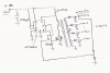
I am currently working on a computer controlled vacuum tube tester project. To perform a couple of different tests I need a number of stable high voltages (250V/200V/180V/130V/90V). The supply should be able to deliver about 50mA max. I have no experience with the design of power supplies, so it would be great if someone could give me some advice on where to look for some ideas, tips & tricks, what components could be interesting etc…

Looking forward to your response!

With kind regards,
Joe
 
Hi. Because you have many high fixed voltages, a flyback converter would be a suitable topology. If each output provides 50mA, you have a maximum of 42.5W needed to be converted.

If you're powering it from a 12VDC source, then the attached schematic might work for you. Only one output is regulated, but all others should track; you should connect the feedback to the supply rail that has the largest current load.
 

Attachments

  • flyback multitap.png
    flyback multitap.png
    30 KB · Views: 281
If only one voltage is used at a time, then the maximum output power would be 12.5W. For that you could use a flyback converter with a single output and a variable voltage adjustment using either a pot or a selector switch with a different voltage adjustment resistor at each position.
 
Are the supplies required simultaneously or sequentially?
 
Those all sound like common voltages that you could get from the main power transformer from an old vacuum tube type TV.

The second option is to only produce one or two of the voltages from a transformer then use power resistors and voltage regulator tubes to get the next nearest lower ones.

250 VDC from one source with 200 and 180 off of it from regulator tubes and 130 and 90 from the other.
 
None of the old valved TV's I came across had a main power transformer - just a big fat ballast resistor to give the voltages direct from the mains - good source of a ceramic tube to finely sharpen knives with if you unwind one!

You must be talking pre ballast resistor days here, tcmtech, - which must have been before colour TV was invented, surely?
 
I think thats because you UK guys have 220 - 240 VAC available from the plug which when rectified can easily produce enough DC voltage for most any tube to work properly.

I have cannibalized enough of the old vacuum tube based ones to know that most US made ones had a large power transformer in them or at least the ones we had did. Being 115 - 120 VAc here its almost mandatory to have to step everything up first.

Growing up as a kid we had a number of old color TV's that were largely vacuum tube based. The oldest one was a 29 inch zenith console style and it had around 15 - 20 of them!
 
Hey people!

Thanks for your replies!! Maybe I can explain the situation a bit more.

I am designing a computer controlled tester for triode tubes. I currently designed circuits for gm, emission, µ, etc.. and currently working on a circuit for cathode-heater leakage detection. I pretty much have all the low voltage stuff covered: opamp supplies, programmable bias, programmable heater supply etc..

Now the challenge is making a supply that can deliver about 50mA max at 250V/200V/180V/130V/90V for all these tests. I am using only ONE of these voltages at the same time. The tester itself is filled with modern solid state components, my goal is not to make an 'old school' tester.. Also if possible, I would like to make the design as cheap as possible..

I have considered ordering 5 kilometers of copper wire to try to make a transformer with these voltages myself, but I would like to do this only if nothing else can do the trick. :D

If the supply circuit has many outputs, I will need to build a switching mechanism, which is an extra cost. So if the supply circuit only has one output, the circuit can be a bit more expensive because of the savings on the switching circuit.

About the flyback converter: that looks like a neat circuit! Thanks! I am just wondering if it wouldn't be better in my case to start with a high voltage transformer?

I hope this all makes sense to you.. I have fairly little experience.. (Only designed and built one guitar amplifier before :) )

By the way, I am in continental Europe, so I get 230Vac from the plug..

If you would like more information, or if you're just interested in my project, just ask!!

With kind regards,

Lebowski
 
I am just wondering if it wouldn't be better in my case to start with a high voltage transformer?
You could start with a 1:1 isolation transformer (you will need isolation regardless of your methodology), rectify and smoothe, then drop the volts with a power FET as needed, under micro control. The FET would be heatsinked (heatsunk??) to handle ~ 12W max.

Edit: To reduce risk of electrocution from those high voltages, could you manage with fewer mA and current-limit at, say, 20mA?
 
Thanks Alec!

I looked that up, and found a relatively simple circuit, that does exactly what I need:

the-variable-high-voltage-power-supply-0-300V.jpg

I was thinking about controlling the voltage by using a digital potentiometer, but this seems rather difficult with these high voltages. Is there any way around this?

I simulated this circuit, and it has a sawtooth-like ripple on the output. I am using the voltages for fairly high impedance loads. I thought about using a smoothing capacitor, but I'm afraid the initial surge current might destroy parts of the circuit (like the control part) Is there any other way to reduce the ripple on this circuit?

Looking forward to your response !

Joe
 
Back in the old days, people would make supplies like the one you are mentioning, using an 0A2 glow tube as a reference, a pair of 6550 as the series pass tubes, and a 12AX7 as the error amp...and of course, a pair of 5U4s as the rectifiers.

I should have a schematic of something like that somewhere...and I'm certain that many of the tube functions can become solid state. It would be interesting!
 
Have you seen the uTracer?

https://www.dos4ever.com/uTracer3/uTracer3.html

The developer states, "The basic idea behind the uTracer is that in order to measure the anode and screen currents, it really isn’t necessary to have the tube switched on all the time. With this I obviously don’t mean the heater, that one has to be on at least a minute or so to stabilize. What I refer to are the high voltages: they only need to be applied to the tube a fraction of a second before the currents are measurement, and they can be switched off immediately afterwards. "

He uses a computer controlled boost converter.
 
Here you go. Output voltage adjustable ~ 30V-300V at up to 50mA with low ripple. Current-limited at ~ 65mA.
AdjustableHighVoltageSupply2.gif

Edit: The adjustment pot could be a digital one, controlled by a MCU.
BEWARE HIGH VOLTAGE. Take all necessary precautions.
 

Attachments

  • HighVRegMod4.asc
    5 KB · Views: 169
Last edited:
Status
Not open for further replies.

Latest threads

New Articles From Microcontroller Tips

Back
Top