Continue to Site

Welcome to our site!

Electro Tech is an online community (with over 170,000 members) who enjoy talking about and building electronic circuits, projects and gadgets. To participate you need to register. Registration is free. Click here to register now.

  • Welcome to our site! Electro Tech is an online community (with over 170,000 members) who enjoy talking about and building electronic circuits, projects and gadgets. To participate you need to register. Registration is free. Click here to register now.

VA Rating

Status
Not open for further replies.

ibwev

Member
When I power the attached circuit through the batteries, the circuit works nicely. When powered through the 40 VA transformer, the light and siren function very poorly. Is the following math correct (assuming 60% power factor)?

Amps= (VA* PowerFactor)/Volts
=(40*0.60)/13.9
=1.7 amps

If the calculated amps is correct, then why is the circuit having problems operating the light and siren which pull less than half (620 mA) the rated amperage?
 

Attachments

  • VA Question.png
    VA Question.png
    34.6 KB · Views: 168
I think you're completely wasting your time even considering power factor.

However the diagram is so poorly and confusingly drawn that it's difficult to tell what it's doing - never mind if it's connected properly.
 
Your current limited rather than VA limited. 40/24 is 0.6A. and that's considerably less than the (40*0.6)/24 or about 0.36 A that your transformer can deliver. I think the 0.6 is the right number. The siren might also have a surge current that is needed to be supplied as well. I ran into this issue.

Aside.
9 * 1.5 does not equal 1.5 V
You should have a decoupling cap close to the regulator.
Relay polarities are confusing. I know sockets are marked that way.
 
Your voltage is too high so the transformer and LM317 voltage regulator are frying.
If your transformer is 24VAC then its peak into the rectifier bridge is 34V. The 40VA transformer will be overloaded when the DC current is more than 40VA/34V= 1.18A.
 
I could replay before AG's post, but he's right too. The transformer voltage is too high, For a full wave bridge, the voltage approaches √2 * Vac.
 
Thank you all for your time. Hobbyist, like myself, really appreciate the help. I apologize for the poorly written schematic. I tried to improve on it.

The 40VA transformer will be overloaded when the DC current is more than 40VA/34V= 1.18A.
The 2 most demanding components in the schematic are the light and siren with a total of 0.62 Amps. Is this too close to the maximum allowable current of 1.18A?

Your current limited rather than VA limited. ....... The siren might also have a surge current that is needed to be supplied as well.
Is my problem that the components may have surges higher than the transformer and/or voltage regulator will allow?

Aside.
9 * 1.5 does not equal 1.5 V
Made correction. Thank you.

You should have a decoupling cap close to the regulator.
Do C1 and C2 not serve as a decoupling capacitor?
 

Attachments

  • VA Question.png
    VA Question.png
    27.1 KB · Views: 147
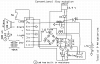
Ci and Co in fig 7 here https://www.google.com/url?sa=t&rct...CmnUPkZ9qd8A&bvm=bv.72197243,d.aWw&cad=rjaare decoupling and MUST be mounted close to the LM317T. So, C1 - yes. Confusing drawn schematic like Nigel said.

The DC voltage will be about 33.6V (24 * 1.4) if it's indeed 24V. It's close the absolute max input of 40 V. Surge suppression is in order for a reliable circuit.

The regulator will drop about (33-12 V) * 0.6A or 12 W. The regulator might be getting too hot and shutting down. It will limit start-up currents to 1.5 A.
The temperature and actual output should be looked at under load. You have to have a minimum of 3V across the regulator for the regulator to work.

Here https://www.google.com/url?sa=t&rct...FEfkADk5oUMa3KwjgqL3-YA&bvm=bv.72197243,d.aWw your looking at full wave-capacitor input, and you do get a derating of the current x 0.62. 40/24*.062 is about an amp, so you should be OK.

I'd like to know what part number you used for the bridge and which you used for the alarm.

The most likely cause is that the regulator is shutting down thermally, not heat sinked properly and definately the secondary voltage is too high.
Vsec should be > (13.9+1.2+3)/1.4 or about 12.96 VAC. Those numbers come from sqrt(2) which takes and RMS voltage and gets a 0-peak value. The 13.9 V is what you want to regulate at. The 1.2 is the voltage drop of 2 diodes in the bridge and 3 V is required for regulation. As you can see, your transformer is about 2X the voltage required.
The circuit should be happy with a 40 VA 12 or 12.6 V transformer.

You could try feeding it with DC from a laptop power brick which is about 19V or so and see if the circuit behaves. You can feed the DC into the bridge rectifier.

There are other losses from rds(ON), but they should be ignoreable.

So, I'll bet the regulator is getting too hot.
 
Status
Not open for further replies.

Latest threads

New Articles From Microcontroller Tips

Back
Top