Continue to Site

Welcome to our site!

Electro Tech is an online community (with over 170,000 members) who enjoy talking about and building electronic circuits, projects and gadgets. To participate you need to register. Registration is free. Click here to register now.

  • Welcome to our site! Electro Tech is an online community (with over 170,000 members) who enjoy talking about and building electronic circuits, projects and gadgets. To participate you need to register. Registration is free. Click here to register now.

Using Xformer For HVDC Bias

Status
Not open for further replies.

dknguyen

Well-Known Member
Most Helpful Member
Hi. FOr an electrostatic ultrasonic driver, I have a transformer that will let me produce a 400Vpp from a 5V signal. The transducer has to have a 150-200V bias however. I think there's a way to use diodes and capacitors on the secondary side to produce this DC bias from the 5V signal while also passing the AC signal to drive the transducer, but I can't figure how what it is. Does anybody have any ideas?

This is the transformer
https://www.electro-tech-online.com/custompdfs/2007/11/ranging20transformer20spec.pdf

The datasheet says secondary voltage ~400V with a 5 VDC primary supply voltage which doesn't make too much sense to me...I had assumed it is either referring to a 0-10V square wave which has a 5VDC component in it, or a 0-5V square wave...I'm not quite sure. Perhaps it is referring to the DC current that the primary can handle (at the specified duty cycle of 2%?)

This may be a silly question also, but when it says duty cycle of 2%, how do you know what time frame it's referring to? Since you could have something running for 2 hours continuously and then 98 hours off periodically and it still might be considered a 2% duty cycle (debatable).
 
Last edited:
2%

SensComp is not very forthcoming with information.

2% duty cycle question:
2% over 30mS. The transformer is used in a sonic application just like radar (sonar). Through the transformer a large amount of power is sent out for a very short period of time. Then for 30mS the receiver listens for the echo to bounce back.

The transformer cannot take 5VDC and make 400VPPAC. The 5 volts must be switch on/off or A.C. The application note shows a transistor that applies 5V to the primary for a short time. When the transistor opens the primary voltage reverses, flys-up to a voltage much greater than 5 volts (opposite direction), then rings.

With no load the transformer will last 100%. In the application note they are trying to get POWER to the transducer. At that power level 2% duty cycle is all you get.

What transducer are you using?
 
THeir 600 series transducer:
https://www.electro-tech-online.com/custompdfs/2007/11/60020environmental20spec.pdf

I was thinking of using an H-bridge to feed a zero DC 50kHz square wave into a LC resonant filter to filter the 50kHz square wave into a 50kHz sinusoid where it enters the transformer, and then using a full-wave rectifier on the secondary to get a 50kHz full-wave rectified signal and use the DC-component as the bias and the fundamental AC component as the signal. I'm not sure how to retain that bias for the receive though (I guess the capacitance of the transducer might hold it long enough during the receive phase).

Your opinion on the app note was that it uses inductive flyback? I was thinking it was pulsing a square wave through the primary on the transformer that gets stepped up. I suppose your explanation does make more sense for the 5VDC parameter and why the dots on the coil's schematic are reversed in polarity. Not quite enough to completely convince me though. If it was the flyback method, then you would need flyback diodes on the primary wouldn't you? And wouldn't the voltage produced be dependent on the di/dt (which isn't specified).

A flyback drive circuit I found was this:
**broken link removed**
except it uses an inductor and not a transformer. I suppose it would be the same with a transformer, except the flyback voltage would be stepped up even higher on the secondary side? I'm not certain about how a transformer behaves with a square wave (does the square wave voltage just get stepped up the exact same way as a sinusoid does?)
 
Last edited:
Look for a schematic for a depth sounder. Here is a link to an old HeathKit unit:
https://www.vintage-radio.info/download/download.php?dir=heathkit&file=mi-29.gif
C11 and L2 form a tank circuit at the resonant frequency of the transducer. Q8 is operated as "class C" and supplies current pulses to the tank circuit to ring it.
This circuit uses a piezo type transducer; can't you find a piezo type that'll work? That way you can avoid the DC bias issue.
Here is another simple circuit:
https://www.micro-examples.com/public/microex-navig/doc/090-ultrasonic-ranger.html
You should be able to add DC bias like this. D1 would have to be a fast silicon diode and R1 could be a very large 1-10M:eek:
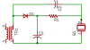
hm: because of the high impedance of electrostatic devices. If C1 is large enough, and R1 is high enough, it should hold it's charge between Tx pulses:
 

Attachments

  • xducer.png
    xducer.png
    2.2 KB · Views: 254
Last edited:
I wouldn't be asking questions if I was using a piezo since my main problem is providing the high voltage bias. If I was using a piezo, I'd probably just go out and buy a $20 module from Devantech anyways. I wanted a flatter frequency response and higher sensitivity though.

There was also the issue of ringing. ELectrostatics transducers don't operate using resonsance like piezos so you can get a closer minimum range than piezos with single transceiver operation.

It just comes down to me liking how electrostatic transducers operate more than piezos.

In your DC bias circuit, won't some of the driving AC signal be lost through that DC storage capacitor reducing the drive at the transducer?
 
Last edited:
In your DC bias circuit, won't some of the driving AC signal be lost through that DC storage capacitor reducing the drive at the transducer?
Yes, but once C1 is charged up, the only losses should be from the very small DC current that the electrostatic transducer needs (I don't see any DC current requirement spec'd on the datasheet). You would size C1 so that it would maintain most of it's charge between Tx pulses so that the bias voltage is there for the Rx part of the cycle. C1 would only significantly load the output for the first few Tx pulses at turn on of the system.
 
I think I'm sloowwly understanding how everything is supposed to work.

From the sample schematic (far bottom right where the transducer is):
https://www.electro-tech-online.com/custompdfs/2007/11/650020module20spec.pdf

It seems that the transformer is working more like a flyback inductor (with the transformer step-up) to provide the high voltage drive, rather than operating like a normal step-up transformer as I originally thought.

THe PDF also mentions that at the end of the 16 pulses that are transmitted, a 200VDC bias remains on the transducer for the receive operation. Is C5 just there to stop the transformer's primary from draining away the charge (and killing the DC bias) that's in the capacitance of the transducer during the listening phase?

It seems that might be easier on the transformer, as far as initially charging up C1 in kchriste's DC bias circuit goes.

EDIT: On second thought, maybe C5 acts as a DC-bias storage capacitor (rather than a DC-blocking capacitor to retain the DC-bias charge on the transducer capacitance). DUring the listening phase the primary side of the transformer is open circuited so the secondary would appear as a small series combination of winding resistance + winding inductance (appearing as a DC short) which are in parallel with the capacitance of the transducer plates?

EDIT2: I think the thought in my first edit is wrong since the polarity of the charge on C5 and the transducer places aren't charging each other, they are facing the same way the capacitors discharge through the seconary winding resistace of the transformer- which leaves me at a loss as to how the circuit is able to retain the DC bias on the transducer capacitance for long enough since it just gets leeched away by the transformer secondary winding resistance. C5 also seems to form a capacitive divide with the transducer capacitance so I have no idea how it works anymore.
 
Last edited:
I think your first EDIT is the right one: during the 16 pulses; C5 with the zeners acts as a DC clamper circuit. C5 is charged up when the zeners conduct in the forward (not zener) direction creating a DC offset to the AC waveform. When the Tx transformer goes dormant, it acts as a DC short putting C5 in parallel with the transducer and thus supplying a DC bias during Rx.
 
Problem is I can't see how current ever flows in the zener forward direction. During the flyback voltage spike current flows out of pin 3. The transformer has a dot at pin 1 and a dot at pin 3 so the current. At least in their circuit. If I built it myself It wouldn't be hard to drive it with an H-bridge to cause a spike in the reverse current direction.

Maybe I should just ignore their reference circuit and use an inductor from DIgikey as the source of flyback rather than their transformer...bah, I don't think you can without a transformer for 400Vpp just because a transistor that can safely withstand that is too hard to find.
Even if I could find one...
In this,
**broken link removed**
The transducer in that schematic is the 500 ohm resistor. They used a sample piezo transducer whose impedance was listed as 500 ohms for their inductance calculations. THe 500 ohms was empirically measured. THe capacitance is listed at 1100pF at 40kHz which works out to an impedance of around 5000 ohms, so I'm not sure what was going on there. I'm not sure if it will behave the same way if I have a capacitor their instead (as the electrostatic transducer). The calculated impedance (500pF at 55kHz) is like 6000 ohms. I'm kind of afraid of an unpredictable tank circuit forming during the flyback, except that the transducer isn't just a capacitor- it's a transducer and therefore dissipates energy somehow and might stop an oscillation from forming. I just don't know how to represent an electorstatic transducer as anything other than a capacitor.

I need to find a book...or something.
 
Last edited:
The transformer has a dot at pin 1 and a dot at pin 3 so the current. At least in their circuit.
The phasing dots are pretty tiny. I didn't notice them at all at first. :eek: The voltage on the secondary of the transformer should reverse polarity due to inductive kickback. C5 should develop a DC voltage across it so that the voltage across the transducer swings between Vz and Vf of the zener diode. Maybe they are using it as a pulse transformer instead of a flyback? They don't mention the turns ratio of the transformer so we can't even guess at the voltages.
THe capacitance is listed at 1100pF at 40kHz which works out to an impedance of around 5000 ohms, so I'm not sure what was going on there.
It probably has something to do with the plates of the "capacitor" vibrating in the air. It would be hard to simulate with basic components.
I need to find a book...or something.
Good luck. Maybe a competitors website has more info?
 
???

I coujld have sworn I posted a response to this. Maybe I closed the window before posting? Here goes again...

I got a response from Senscomp finally. THey say that the transformer is meant to be driven by a 50% duty cycle, 5V, 50kHz square wave in bursts of 1-20 pulses that will appear as 400Vpp on the secondary. A 100-200ms rest period is required between pulse trains. The zeners are just for voltage clamping.

I think I know how the DC bias is being formed now. It's dumb really, but it has finally registered in my mind that the transformer's secondary is tied to ground so the square wave going into the transducer has a 200VDC bias. I don't know why I never noticed this before. I still don't know what the 2200pF capacitor in parallel with the transducer does though- it seems to me it's just a capacitive divider that would cut down the required voltage to the transducer by 1/5th. I still do not know why it is there. Nor am I entirely certain how the transducer holds onto the charge for long enough during the listening phase since one would think the transformer secondary would completely drain away the DC bias charge from the transducer very quickly.
 
I still do not know why it is there. Nor am I entirely certain how the transducer holds onto the charge for long enough during the listening phase since one would think the transformer secondary would completely drain away the DC bias charge from the transducer very quickly.
It's there so the charge DOESN'T drain away. I've cut the relevant section out and added the input to the receiver as a short (in red) since it is just back to back diodes as far as the transmitter is concerned. Now imagine that you put your 200Vdc power supply across J2 (+) and J3 (-). No current will flow once Cx and C5 are charged up (They are effectively in DC parallel via the transformer). They will remain charged once the power supply is removed and will only discharge via their own leakage currents and that of the zeners.
 

Attachments

  • xducer.PNG
    xducer.PNG
    40.2 KB · Views: 254
Last edited:
But the initial current flows through the two capacitors in series (not parallel), so once you stop the pulses, C5 and the transducer's voltage is adding up in series (or in parallel but their voltages add up rather than oppose each other to stop charge from leaking) where it just empties out over the short formed

At least, that is what I see. PLus, there's also the thing about the capacitive divider being formed for the AC signal. THat's my interpretation. What do you see exactly?
 
I got a response from Senscomp finally. THey say that the transformer is meant to be driven by a 50% duty cycle, 5V, 50kHz square wave in bursts of 1-20 pulses that will appear as 400Vpp on the secondary.
Let's say that the red Rx diodes/J3 in the diagram are ground. So, in effect, the voltage at pin 3 of the transformer (connected to C5) swings between +200V and -200V. Because of the 4 91V zeners, the voltage at J2 swings from 364V to -2.8V meaning there is an apx 164V to 197V DC voltage developed across C5 due to the rectification of the zeners. Because Cx is only 1/5 of C5, it forms a bit of a divider, but the diodes can still unbalance the current flow in/out of C5 creating a DC offset equal to the zener voltage. When the pulses stop, this DC voltage remains and the charge is distributed between C5 and Cx.
 
Last edited:
Status
Not open for further replies.

Latest threads

New Articles From Microcontroller Tips

Back
Top