Continue to Site

Welcome to our site!

Electro Tech is an online community (with over 170,000 members) who enjoy talking about and building electronic circuits, projects and gadgets. To participate you need to register. Registration is free. Click here to register now.

  • Welcome to our site! Electro Tech is an online community (with over 170,000 members) who enjoy talking about and building electronic circuits, projects and gadgets. To participate you need to register. Registration is free. Click here to register now.

Using timer 2 on atmega328

Status
Not open for further replies.

MacIntoshCZ

Active Member
Hello there,
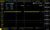
i would like use timer 2 on avr, but i probably made somewhere a mistake or avr is faulty becouse i am getting square wave about 95%duty cycle.
I already succesfully used timer 0.
I should get 100Khz square wave, 50% duty cycle, on pin 11. Thanks for help
Here is code:


void setup() {
TCCR2A = 0;
TCCR2B = 0;
TCNT2 = 0;
TCCR2A |= (1 << WGM20) | (1 << WGM21);
TCCR2B |= (1 << WGM22);
TIMSK2 |= 1;
TCCR2A |= (1 << COM2A1);
TCCR2A |= (1 << COM2B1);
OCR2A |= 160;
OCR2B |= 80;
pinMode(3, OUTPUT);
pinMode(11, OUTPUT);
TCCR2B |= (1 << CS20);
interrupts();
}


void loop() {

}
 
In my case its not working. I think my arduino uno timer 2 is defective. I tried that code but nothing seems to happen.
 
I wrote it on timer 1. It definitely something does. It still acts very strange. Like my level trigger is gone mad.
void setup() {
pinMode(9,OUTPUT);
pinMode(10,OUTPUT);
TCCR1A = 0;
TCCR1B = 0;
TCCR1C = 0;
TCNT1 = 0 ;
TCCR1A |= (1<<WGM10) | (1<<WGM11);
TCCR1B |= (1<<WGM12) | (1<< WGM13);
TCCR1A |= (1<<COM1A1) | (1<< COM1B1);
OCR1A = 160;
OCR1B = 80;
TIMSK1 = 1;
interrupts();
TCCR1B |= (1<<CS10);


}


void loop() {

}
 

Attachments

  • DS1Z_QuickPrint8.png
    DS1Z_QuickPrint8.png
    42.7 KB · Views: 282
Using brightness on an LED

C:
int ledPin = 9;      // LED connected to digital pin 9
int analogPin = 3;   // potentiometer connected to analog pin 3
int val = 0;         // variable to store the read value

void setup() {
  pinMode(ledPin, OUTPUT);  // sets the pin as output
}

void loop() {
  val = analogRead(analogPin);  // read the input pin
  analogWrite(ledPin, val / 4); // analogRead values go from 0 to 1023, analogWrite values from 0 to 255
}
 
I should get 100Khz square wave, 50% duty cycle, on pin 11.

See if you can run this to get 200kHz PWM with 50% duty cycle on pin 3.

Code:
#include <avr/io.h>
#include <util/delay.h>

int main(void)
{
  pinMode(3, OUTPUT); 
  TCCR2A = _BV(COM2A1) | _BV(COM2B1) | _BV(WGM21) | _BV(WGM20);
  TCCR2B = _BV(WGM22) | _BV(CS20);
  OCR2A = 80;
  OCR2B = 39;
  while (1);
}

See:
**broken link removed**
 
For Rogers:
I know this function. But its not powerful enough for me. I want to know exactly what its going on. This is "black box" function.
 
See if you can run this to get 200kHz PWM with 50% duty cycle on pin 3.

Code:
#include <avr/io.h>
#include <util/delay.h>

int main(void)
{
  pinMode(3, OUTPUT);
  TCCR2A = _BV(COM2A1) | _BV(COM2B1) | _BV(WGM21) | _BV(WGM20);
  TCCR2B = _BV(WGM22) | _BV(CS20);
  OCR2A = 80;
  OCR2B = 39;
  while (1);
}

See:
**broken link removed**
I tried exactly this code and i got zero volts on pin 3 =). I really thing that my arduino is messed up.
A will try to use atmega8/32/128 instead in standalone circuit. I dont have another arduino.
 
Using brightness on an LED

C:
int ledPin = 9;      // LED connected to digital pin 9
int analogPin = 3;   // potentiometer connected to analog pin 3
int val = 0;         // variable to store the read value

void setup() {
  pinMode(ledPin, OUTPUT);  // sets the pin as output
}

void loop() {
  val = analogRead(analogPin);  // read the input pin
  analogWrite(ledPin, val / 4); // analogRead values go from 0 to 1023, analogWrite values from 0 to 255
}
Even this function not works.
analogWrite(3,500);
So i assume my arduino is KO
 
I tried exactly this code and i got zero volts on pin 3 =). I really thing that my arduino is messed up.
A will try to use atmega8/32/128 instead in standalone circuit. I dont have another arduino.

Using my toy oscilloscope, I just got this:
PWM200kHz.jpg


That speed is at the maximum specified for the toy scope, so I didn't expect to see much, but the stats are about right.

When I slow it down with
Code:
  OCR2A = 254;
  OCR2B = 127;

I get this, which is a pretty decent waveform considering it is a $30 scope.
pwm67kHz.jpg


Of course, I may have messed something up, but I highly recommend those two references that I posted, plus the data sheet.
 
Thank
Using my toy oscilloscope, I just got this:
View attachment 121390

That speed is at the maximum specified for the toy scope, so I didn't expect to see much, but the stats are about right.

When I slow it down with
Code:
  OCR2A = 254;
  OCR2B = 127;

I get this, which is a pretty decent waveform considering it is a $30 scope.
View attachment 121391

Of course, I may have messed something up, but I highly recommend those two references that I posted, plus the data sheet.
Thanks for help. I should buy new arduino
 
Even this function not works.
analogWrite(3,500);
So i assume my arduino is KO
That code is outputting PWM on pin 9 not pin 3... Pin 3 has a pot to change the PWM on pin 9..

500 is tooo high... 256 means 100%, 127 means 50% and 0 means 0%...
 
Status
Not open for further replies.

Latest threads

New Articles From Microcontroller Tips

Back
Top