Continue to Site

Welcome to our site!

Electro Tech is an online community (with over 170,000 members) who enjoy talking about and building electronic circuits, projects and gadgets. To participate you need to register. Registration is free. Click here to register now.

  • Welcome to our site! Electro Tech is an online community (with over 170,000 members) who enjoy talking about and building electronic circuits, projects and gadgets. To participate you need to register. Registration is free. Click here to register now.

Using one button count up/one button to count down using 4510

Status
Not open for further replies.

pageygeeza

New Member
I've seen this question asked a couple of times on here, but I couldn't fathom out the answers. I've only been messing with logic circuits for a short while so i've still loads to learn.

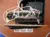
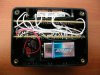
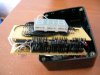
The main guts of the circuit runs very well, but I need to simplify the counting direction. I need one button to increment by one and the other button to decrement by one. I'm using tactile button switches for this job and I can get the correct pulse going into the clock from the button using the pull-down resistor. But i'm also using that signal from the same switch to determine direction. I originally assumed that because the signal from the button would become high, it would send a high state into pin15 to make it count up, but it only counts down. I'm probably going about this the wrong way, but any help would be truly appreciated. In the end I'm trying to get a device with only three buttons: Count up, count down and reset. Rather than having a switch for direction a button to count and a reset switch.

Thanks in advance,

Daz
 
The 4510 needs a logic high to count up on pin 10 and logic low to count down.
 
Have a look here.
**broken link removed**
 
Oooops, my mistake, just realised what I put there. I did mean pin 10 for the count direction, lol. Is it still possible to do? Does a high state have to go to pin 10 before pin 15 to count up? And it that is the case, is it possible to do it without over complicating the circuit?
 
Pin 10 = +V counts up, a 0v for count down, so check the link I gave. You can make a toggle type circuit which will do what you need...
 
I can understand what you're getting at, but basically the latch would be doing the same thing as the switch? I'm not sure I explained myself properly, I need one button when pushed to count up and the other button to count down, rather than having a button to toggle witch direction to count. You have to remember i'm still a newbie at this, so you might need to explain a bit better. :D

Thanks
 
Another option. The input RC networks provide switch debounce. Since pin-10 on the 4510 needs to be high before the clock for an UP count, the upper RC network and the Schmitt NANDs provide a slight delay on the rising clock edge. Pin-10 is high when the clock arrives. On the down count, Pin-10 is already low. The lower NANDs provide a fast rising edge to the clock pin. The diodes make an OR gate to steer the UP and Down clock pulses. I have not built this, so any comments on glaring flaws are welcome. ;)

Ken
 

Attachments

  • ClkUpClkDown2.gif
    ClkUpClkDown2.gif
    15.7 KB · Views: 384
Last edited:
Right, just tried it out and it works, but there is a niggling problem. Countdown works perfectly, (that i'm aware of.) But sometimes countup doesn't register a button press, (not sure if it's my wiring or not.)

Actually, it seems to be working 100% now, (my tactiles don't fit onto the breadboard too good, so that could've been it.)

Thanks again bud, you've been a great help :D
 
Ooops, meant to have got back sooner. My counter has been completed and put into a nice case. It can count up to 999 as i didn't have the space to put anymore components in. Iirc the 2 veroboards are 12x36 holes, one contains the display and resistors and the other contains the 7 ic's. There was one problem though, after i'd roughly put it together it wouldn't count properly, but considering i'd been on it for hours that day i wasn't going to let it get to me, so i left it for the night. After a brainwave the next morning, i thought i'd check all the power rails. I found the problem, the 0v pin on the nand chip wasn't connected, oops. would explain why it was going mental!! That fault was from when i was drawing up how the connections were going to be made, i'd actually missed the connection at that point. Apart from that 1 connection the circuit worked perfectly! So, many thanks to everyone that helped and i'll get picks posted soon. :D
 
Congratulations! How about a picture? :)

Ken
 
As you can see, space was very limited on this project!! The main rails were run underneath the dil sockets. ;)

Most of the resistors for the display are under the display itself. I was gonna take a pic of the soldering, but I have to admit, it's a bloody mess! :p

I was using veroboards that have track breaks every 3 holes, (It was very convenient for my project, dunno if it's classified as cheating or not.) ;)
 

Attachments

  • DSCN2085.JPG
    DSCN2085.JPG
    85.9 KB · Views: 230
  • DSCN2080.JPG
    DSCN2080.JPG
    83.7 KB · Views: 219
  • DSCN2084.JPG
    DSCN2084.JPG
    78.1 KB · Views: 217
  • DSCN2077.JPG
    DSCN2077.JPG
    64.7 KB · Views: 211
  • DSCN2078.JPG
    DSCN2078.JPG
    69.7 KB · Views: 207
  • DSCN2069.JPG
    DSCN2069.JPG
    1.4 MB · Views: 272
Looks good!

dunno if it's classified as cheating or not
When "you" set the specs for the project, there is no cheating. ;)

What are you going to do with the counter?

Ken
 
Last edited:
It was purchased with the track breaks. :eek:

It was just a little project to do, just to make sure I know what i'm doing. I was going to use it as a counter to count the winds on a machine that winds coils, but i'm not following that route anymore. I need some electronic skills for a major project I have yet to start. The good thing about the counter is that I can make external connections to operate the counter. Makes life a whole lot easier. :D
 
Let us know about your "major project" when you get there. Love to see what other people are doing.

Ken
 
Status
Not open for further replies.

Latest threads

Back
Top