Continue to Site

Welcome to our site!

Electro Tech is an online community (with over 170,000 members) who enjoy talking about and building electronic circuits, projects and gadgets. To participate you need to register. Registration is free. Click here to register now.

  • Welcome to our site! Electro Tech is an online community (with over 170,000 members) who enjoy talking about and building electronic circuits, projects and gadgets. To participate you need to register. Registration is free. Click here to register now.

Using MikroBasic to make LED chaser effects

Status
Not open for further replies.

bigal_scorpio

Active Member
Hi to all,

I am still learning to use PIC micros and am using MikroBasic from Mikroelektronica.

Most of my projects I just learn how to do by trial and error and most of the time I am successful (sometimes after months though) and they work out in the end.

However I am stuck on something that I thought would be simple until I tried to do it!

I made my first LED chaser years ago using logic chips and recently saw one on u-tube that I thought was stunning. I have posted the link below.

What I can't get my head round is how the program makes such effects, if its an algorythm then its beyond me.

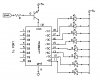
I have built a 32 LED chaser using a PIC16F887 and it works fine simply as a chaser but I don't have a clue how the different effects are made.

Can anyone explain the way or ways to do this in software? I am not asking anyone to write the code for me, just give me a push in the right direction.

Edit, I don't want to have all the options that the fusion light has, just the pattern between 31 and 34 seconds would do me nicely.

Thanks Al
YouTube - Fusion Core Light - 1
 
Last edited:
I made a simple pdf that should get you started in the right way

Hope it helps
 

Attachments

  • leds scan.pdf
    122.7 KB · Views: 525
Last edited:
Got a bit further

Hi Burt,

Thanks for the PDF. It has got me going in the right direction but mine does not look like the fusion one I posted. I am guessing he has somehow incorporated PWM into the mix somehow.

Any idea on this? Wondering how he keeps track of the different PWM ratios on the LEDs. His seems to have a dimmer trail of following LEDs that tapers off really nicely and makes the general effect look much better than mine. Or is it just POV and the way he filmed it?

Any help appreciated Al
 
The PIC doesn't have that many PWM channels.
That is a meaty PIC with a fair amount of pins, probably a TQFP100, so addressing the LED's individually probably isn't an issue.

I guess you can vary the time each LED is on and off, maybe thats how the PWM effect is done?

If you look at the video close enough you can see that the dimming doesn't happen to all of them at the same time, so that would indicate some kind of software PWM I would think.

Wilksey
 
Last edited:
Hi mate,

Yeah, I was sure that the Fusion used software PWM. What gets me is keeping track of all the pins that are on and all the different PWM rates at the same time.

Al
 
Looking at the video again he does state each LED is addressed individually and that each LED is PWMed, that chip 64 pin, not 100 as I first saw, maybe it is persistence of vision ;)
A simple array can keep track of each pin and it's PWM value, and rate if required.

Now, that chip has 9 PWM channels, amazing, so I suppose you could have 9 dimming at one time, as long as you dont have more than 9 unless you multiplex, otherwise you will need to use software PWM.

Wilksey
 
There more then likely using a timer and on event killing the leds for a nice software effect.
 
Do you mean like a timer linked to a state machine for the brightness Burt?

I was thinking a timer, but it does actually dim and not just kill, so it would need multiple steps in the timer routine to dim each LED surely? Software PWM if you will, just does it so fast you dont realise.
 
After looking at the video about 4 more times I would say there using pwm and 4 drivers for the leds the fading is broke down to 4 ports if you watch you'll see that.

I'm going to see if I can match it.
 
You think he is using 4 of the 9 hardware PWM drivers in the PIC to drive individual lines or an actual seperate PWM driver?
 
If you look at it, the fading is in banks of 8 leds. So there using 4 pwm channels with Led drivers I didn't put all the parts

But like this
 

Attachments

  • driver2.PNG
    driver2.PNG
    20.4 KB · Views: 630
Ohhh, I see, banked led's.

I suppose you could, to give that "random" effect wire them "randomly".

Good concept though, thats how he did it with a 16F before with that kind of driver obv.

How sneaky of them!

And clever of you for figuring it out!

Nice one Burt! I was also trying to figure out how it was done.

Wilksey
 
It looks like he (the youtube author) is using software PWM per LED. If that's the case, I would use a 32 byte array of duty cycle values, one array element for each LED, and a software PWM driver in the ISR.

Al, do you have a schematic of the 32 LED matrix on your 16F886?
 
Last edited:
I still think its more like this. Because if you look all actions is in 4 he dimmed 8 leds on the four corners at the same time
then fades from left to middle and right to middle at the same time
 

Attachments

  • led_layout.PNG
    led_layout.PNG
    7.4 KB · Views: 429
Hi Burt, Mike and Wilksey,

Burt, you have much more experience with this sort of thing, but it still confuses me if you are right how he keeps track of the pins and PWM when using the 2803?

Mike, as to the schematic, I never made one. My design was just to connect 32 leds to 32 of the O/P pins of the 887, I used the 5 output oins of port A, all ports B, C and D and then 3 on port E, 32 in all. Since I only want one pattern I wasn't concerned about tying up all the pins as outputs, I just intend the pattern to run at power up and not change to other patterns as the video does. Just that one gorgeous pattern will satisfy me nicely!

I almost went for just 2 ports and use 2 LEDs on opposing sides of the ring but the video seems that he has control of both sides separately, at least it looks like it to me, but then again every time I watch the thing I get more confused.

How would your Array idea work, can you give me an example?

Thanks guys.....Al
 
Your just scanning the port pins. For the leds and fading with pwm with the driver. I was going to test this out this week end
 
How would your Array idea work, can you give me an example?

Sure. Here's a Charlieplexed 20-LED circuit with 32 duty cycle levels per LED.


The software PWM driver uses a 20 element array which contains duty cycles values of 0..31 for each LED. You stuff the array in 'main' with the values you want to animate the display.

Here's the code Futz came up with for the pattern shown in the video above (note that LED 0 is top left and LED 19 is bottom right). I had to use very low duty cycle values to keep from overloading the camera. The entire BoostC program listing can be found here.

Cheerful regards, Mike

Code:
//  simple interface to pwm driver using duty cycle values of 0..63

  led[0] = led[19] = 11;    // 11 * 0.3125% = 3.4% of 20% max
  led[1] = led[18] = 7;     //  7 * 0.3125% = 2.2%
  led[2] = led[17] = 5;     //  5 * 0.3125% = 1.5%
  led[3] = led[16] = 4;     //  4 * 0.3125% = 1.2%
  led[4] = led[15] = 3;     //  3 * 0.3125% = 0.9%
  led[5] = led[14] = 2;     //  2 * 0.3125% = 0.6%
  led[6] = led[13] = 1;     //  1 * 0.3125% = 0.3%
  led[7] = led[12] = 0;     //
  led[8] = led[11] = 0;     //
  led[9] = led[10] = 0;     //

  while(1)
  {                         // simple animation demo
    temp = led[0];          //
    while(!last_column);    // sync' to 16.25 msec frame rate
    for(x=0; x<19; x++)     //
    { led[x] = led[x+1];    //
    }                       //
    led[19] = temp;         //
    delay_ms(26);           //
  }
}
 

Attachments

  • LED-20.png
    LED-20.png
    47.3 KB · Views: 711
Last edited by a moderator:
I no this don't really have a lot to do with the LED chaser. But i have tried some cool effects I ordered some white leds

But you can do some real good things with software delays and loops. This is a turn signal light i was working with while I wait
for my leds

Believe it or not the leds are all blinking at 1 mS and it's all software


I just got done doing a Excel chart for my leds for the chaser
 
Last edited by a moderator:
Status
Not open for further replies.

New Articles From Microcontroller Tips

Back
Top