Electro Tech is an online community (with over 170,000 members) who enjoy talking about and building electronic circuits, projects and gadgets. To participate you need to register. Registration is free. Click here to register now.
Welcome to our site! Electro Tech is an online community (with over 170,000 members) who enjoy talking about and building electronic circuits, projects and gadgets. To participate you need to register. Registration is free. Click here to register now.
The cool thing about a lot of these integerated switchers is they're not real sensative to the actual components you use ... just take what you have available and build in on a breadboard, you'll be supprised that it works.
sure, having the actual proper components means higher efficiency and lower ripple, but you can worry about that once you get the prototype working.
I deff like the ON versions of datasheets for a lot of the components TI has ... I wonder how they both have similar products like that. However, TI offers free simulators for a lot of those chips, which can answer more questions than a datasheet sometimes.
thanks for giving me confidence
I have tested one ckt and have succeed in it.
I would like to ask which is more better linear or switching in general sense.
As switching will give rise to switching noise also
and linear will only dissipate.
the only things which are differing are
1>
For Rsc I have used a short wire
2>
I have used 50uH of inductor even I am not sure of its value.
I have inductors but I cannot read their values.
I got 50 by using parallel combination of 100uH but I am not sure they are 100uH or what.
3>Instead of MBR1645
I am uisng 1N5822
Input voltage is 6.4V from a SLA battery. 4.2AH marking
NOW the problem is
1>
when I am connecting a load which just takes 300mA to 400mA the voltages fall from 12V to 6.8V or so
2>
without ouput capacitor and load the voltage at ouput is constant 12V
but when i connect a 2200uF/35V capacitor the voltage fluctuates a little and voltage drop to 11.6 to 11.7Vs
I think this is what they called they need less ESR of capacitor
try a bigger inductor, and make sure it's a power inductor, and not an RF choke
the only 'critical' parts I've run into on these things, is (A) the switch itself and (B) the output capacitor ... you're probably right about the ESR of your 2200uF cap being too high
also, it could be your piece of wire for the osc resistor has the clock running too fast, and the switch and/or diode can't handle it?
also, where is the 6v coming from ... do you have sufficient input capacitance?
I donot know whether it is Rf choke but it is like a 1/2W resistor with color band markings.
I donot know it power handling capacity.
My output falls when i connect load which draws 250mA, and
I burned out one cylindrical shaped sealed inductor on which just rosy was written.
the only 'critical' parts I've run into on these things, is (A) the switch itself and (B) the output capacitor ... you're probably right about the ESR of your 2200uF cap being too high
i am using IRF540 and a 2200uF electrolytic capcitor.
When i connect 2200uf capacitor the output falls from 12V to 11.5V and there are little oscillation in output. output constantly varies from 11V to 11.6V
also, it could be your piece of wire for the osc resistor has the clock running too fast, and the switch and/or diode can't handle it?
I have few more inductors
which are again in shape of resistor but size is near to 1W.
and few inductors which i have look like completely sealed cylindrical they are round like capacitors. notting written on them not even bands.
just they are purple, orange, pink, red etc.
I have searched net and got they are called radial and axial inductors and I have both of them.
I am looking for the inductor values ranging from 10uH to 47uH.
Like Nigel has said, this is an rf choke ... a "power inductor" is usually wound on a torrid or bobbin core, and is larger than an rf choke ... here are some pictures (mainly surface mount) https://images.google.com/images?q=power+inductor ... you can see a power inductor I wound myself in this picture ... it's the green torrid with white wire wrapped around it
i am using IRF540 and a 2200uF electrolytic capcitor.
The IRF540 is a high voltage medium current transistor, rated for between 80 to 100 volts ... and as such, requires substantial gate drive Vgs of at least 20v ... most likely your smps controller is not able to drive the switch fully on. You need a "logic level" mosfet, something with a much lowr Vgs requirement ... IRLR, IRLU, IRL, etc... these are all logic level parts compatible transistors, and don't take 20 volts on the gate, instead they generally take under 10, some as low as 1.8
For the output stage, use a lot of smaller caps in parallel instead of one big cap, this will help to reduce your ESR
the input is from battery 6V,4.2Ah and i have connected 1000uF at input.
i've read so many SMPS datasheets lately, they've all merged together in my head! :shock:
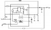
anyway, reading the mc34063a sheet again, I see that both TI and ON recommend the use of an NPN (or PNP) BJT transistor, not a FET.
Looking at the internal diagram, I can see why - the chip doesn't have a "gate drive" totempole, instead, its just a darlington transistor
so, I'd recommend trying something like a medium power darlington... like a TIP31, TIP100, etc... find yourself an NPN in a to-220 package, and plug it into your breadboard, see what happens!
This site uses cookies to help personalise content, tailor your experience and to keep you logged in if you register.
By continuing to use this site, you are consenting to our use of cookies.