Continue to Site

Welcome to our site!

Electro Tech is an online community (with over 170,000 members) who enjoy talking about and building electronic circuits, projects and gadgets. To participate you need to register. Registration is free. Click here to register now.

  • Welcome to our site! Electro Tech is an online community (with over 170,000 members) who enjoy talking about and building electronic circuits, projects and gadgets. To participate you need to register. Registration is free. Click here to register now.

Using CMOS IC's

Status
Not open for further replies.

cassiel

New Member
Can anyone please help me out here.

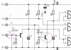
I'm building a device that will switch the rear indicating lights of a car while it's decelerating.

I'm using a 4093 and it runs of 12v from the car, obviously. The problem is that even when I merely touch the supply lines on the breadboard the unit starts oscillating. it's not supposed to, it's merely a logic circuit working from either a positive or a negative. And no inputs or outputs of the 4093 is left floating. Even while I'm typing now it "flashes" every now and then, without touching or doing anything. It's probably a fault or poor design somewhere in the circuit.

Without going to in depth with how the circuit works, what can cause this? Any ideas or tips on using cmos?
 
If you haven’t, try putting a 10 mfd capacitor across the +12v and ground close to your chip to smooth out the power. Your alternator puts out a rectified sine wave so you don’t get a steady dc.
 
Please post the schematic.
 
Yes, I even used a 100uF cap over the supply pins of the IC.

Actualy I've used another NPN transistor. I used to have a BC337 in there, but found it never actually allowed C2 to reach it's maximum voltage, it only got to about 9,5 Volts, instead of about 14V.

So I tried a BC237 and it allowed C2 to charge to just below the supply voltage. It also removed the "oscillating" the circuit seems more stable now.

Here's a quick description of the input side:

If you close the switch between 1 and 2 you turn Q3 on, Q3's resistance falls and shorts C2 to discharge it completely. If you open the switch (1 & 2) Q3 goes high and C2 charges and eventually triggers the Schmitt NAND gate. But with the BC337 C2 never reached the supply voltage and I think the lower voltage bothered the Schmitt, causing it to switch between two states, I think.

On connection 3 you also have a timer which works on supplying 12V and then you get a delay on function.

If you use the BC337, and merely touch connection 2 then the unit starts oscillating. Don't know if the transistor is very sensitive or what. Can you please comment on the timers construction.

Also I don't know much about MOSFETs and I have to switch the globes using a IRFZ44N, but the MOSFET will be connected to the positive then the load (2 Globes) then earth, all in series. I think this called positive switching. Can you recommend a proper way of switching the MOSFET in this manner from the output of hte 4093?
 

Attachments

  • Image1.jpg
    Image1.jpg
    27.3 KB · Views: 266
I can't see why you need Q3. I would connect 1 via R5 to the Schmitt input.

The full circuit is not visible, so I can't see if you have a 100 nF capacitor across the CMOS supply rail. The electro cap is a good start, but it has a high inpedence at high frequencies and thus cannot prevent instability.

Also, I would have instaslled shunt regulator (ie. a resistor and say a 8.2 Volt Zener) in order to run the CMOS at 8.2 V and thus protect it from alternator spikes.
 
I can't post the whole schematic because this actually a patent in development and I have been sworn to secrecy. :)

Q3 is there to ensure that C2 is completely discharged before the next timing sequence starts. I found that C2 discharges to slowly on it's own, and then you end up with a irregular timer.

I’ll add the 100nF across to the IC.

The regulator idea makes sense, but won’t it affect the MOSFET switching? I still need a reliable circuit to switch the MOSFET.
 
cassiel said:
I can't post the whole schematic because this actually a patent in development and I have been sworn to secrecy. :)

Q3 is there to ensure that C2 is completely discharged before the next timing sequence starts. I found that C2 discharges to slowly on it's own, and then you end up with a irregular timer.

I’ll add the 100nF across to the IC.

The regulator idea makes sense, but won’t it affect the MOSFET switching? I still need a reliable circuit to switch the MOSFET.

If you want to discharge the capacitor rapidly you can connect a diode across the resistor (or a diode and resistor in series so the discharge rate is known). The diode can be connected either way. One way it speeds up the charging, the other way it speeds up the discharging. See attachment.

The MOSFET needs sufficient Gate - source voltage to turn it on, so it is a matter of choosing the right MOSFET.
 

Attachments

  • Delay cct.gif
    Delay cct.gif
    3.1 KB · Views: 191
Last edited:
Funny enough, in the earlier versions of the circuit I did use diodes, but they didn't seem to do the trick. That's why I switched to the transistors.

Maybe I did something wrong, I'll build another and see what happens.

Concerning the MOSFET, I have a n channel and it switches on with a positive signal between the source and gate. But say the logic circuit gives a low output that should turn the MOSFET on, can I just substitute the n with a p channel, connected in the same way? I know this is basic stuff, but like I said, I don't know THAT much about electronics. :)
 
I have used the circuit I posted many times.

However, I just re-read your earlier posts. Since you are using a switch, the attachment below will be simpler. The R & C values will give you a delay of about 100 millisecond.

Edit, This is the wrong attachment as it gives symmetrical delays, I'll leave it and post the right one later.

An N channel MOSFET needs a high to turn it on.

What MOSFET are you using?

If you use a P channel, you will have to connect its source to the positive rail and apply a low to the gate to turn it on.
 

Attachments

  • Switch delay & bounce suppress.gif
    Switch delay & bounce suppress.gif
    1.7 KB · Views: 185
Last edited:
Here is the right one.

The capacitor charges rapidly when the switch is closed so the output of the Schmitt goes low after about 1 millisecond.

When the switch is opened, C discharges via the 1M so the output remains low for about 1 second.

I suspect that the reason your circuit with a diode did not work is because you did not include a "pull up" resistor.
 

Attachments

  • Switch & Bounce suppressor 2.gif
    Switch & Bounce suppressor 2.gif
    1.7 KB · Views: 169
I got a IRFZ44N from the local parts shop. They also gave me the idea to use a MOSFET instead of a relay. The time delays are actually in the line of about 2 seconds for the one, and about 6seconds for the second. Both of them is delay on.

I'll get a couple of p channels today, and connect them as you said. So you don't need any supplementary components when using the p channel? I'm not talking about one or two resistors, I mean other parts such as caps or diodes, for stability and such....
 
cassiel said:
I got a IRFZ44N from the local parts shop. They also gave me the idea to use a MOSFET instead of a relay. The time delays are actually in the line of about 2 seconds for the one, and about 6seconds for the second. Both of them is delay on.

I'll get a couple of p channels today, and connect them as you said. So you don't need any supplementary components when using the p channel? I'm not talking about one or two resistors, I mean other parts such as caps or diodes, for stability and such....
The IRFZ44N is an N channel. It would be suitable if you want to use an N channel.

What type of P channel did you buy? Do you really need a P channel?

What does the MOSFET drive? ie. how much current does it have to cope with?

It is advisable to insert a 100 Ohm resistor in series with the gate to ensue stability.
 
well i used to switch the relay with a PNP transistor (BC557), with the output low. But now with the IRFZ44N I have to add an additional NPN transistor used as an inverter.

So i was wondering if I can use a P channel instead and supply it directly from the output of the logic. And ditch the inverter.

It'll drive atleast two 12 Volt globes, a load of about 48W, ie 4amps. So rating isn't a problem. I used a 1K resistor in series with the gate, and from the gate to earth a 47K to ensure there are no floating currents. The N Channel worked ok, but I still have to get the P channel. Any reccomendations?
 
Do you have a spare gate in the 4093? If so, use it as an inverter.

Yes, you can use a P channel, connect the source to +12V and a resistor from the gate to the CMOS output (or the collector of the NPN inverter if you don't have a spare NAND Schmitt). You don't need a 47k to earth since the CMOS switches between high and low (as will the NPN).

The drain current is not the only consideration. You need to be sure that the gate to source voltage is sufficient to turn the MOSFET on at 4 Amp.

If you look at page 2 of the Philips data sheet for the IFRZ44N, the gate threshold voltage is specified as typically 3 Volt at 1 mA. But if you look at Fig 5 on page 4, it shows that the Vgs must be at least 5 Volt for a drain current of 4 Amp.

So before you buy a P channel, look at its data sheet.
 
Last edited:
Thanks alot, I didn't even think of looking at the datasheets!

I don't have a spare gate, so I'll go for the P channel.

Thanks for all the info.
 
I finally got my hands on a IRF9530N.

No time now to test it but looking quickly at the datasheet, it looks like it'll switch 10A at about 7 volts (gate to source) abd judging by the supply and the output of the logic, I don't think that'll be a problem.

I'm going to use the Zener config as suggested and run the circuit of about 9Volts or so. That should give me a high enough voltage on the output to switch the MOSFET.
 
cassiel said:
I finally got my hands on a IRF9530N.

No time now to test it but looking quickly at the datasheet, it looks like it'll switch 10A at about 7 volts (gate to source) abd judging by the supply and the output of the logic, I don't think that'll be a problem.

I'm going to use the Zener config as suggested and run the circuit of about 9Volts or so. That should give me a high enough voltage on the output to switch the MOSFET.
Note that you wont be able to drive the P channel directlyn from the CMOS if you use the Zener regulator unless you use a level shifting circuit.

So you could design a level shifting inverter with an NPN transistor to drive the P channel.
 
well the circuit works great with the p channel, the only other problem, as you say, is the zener business.

Is it then really nessecary to bother with it? Could the alternator's transients be that bad?

What about using a 100uF and 100nF cap to act as a filter, the one to catch ripples, and the other for what ever is left...
 
I'm not an expert in auto electrics, but I recall that about 2 or 3 years ago, someone who is an expert posted a comment that the spikes from alternators can be quite high. I can't recall the figure but I think it was in the hundreds of volts region.

Try searching for "alternator" or "spikes" etc.
 
Status
Not open for further replies.

Latest threads

Back
Top