Continue to Site

Welcome to our site!

Electro Tech is an online community (with over 170,000 members) who enjoy talking about and building electronic circuits, projects and gadgets. To participate you need to register. Registration is free. Click here to register now.

  • Welcome to our site! Electro Tech is an online community (with over 170,000 members) who enjoy talking about and building electronic circuits, projects and gadgets. To participate you need to register. Registration is free. Click here to register now.

using assembly in mplag/junebug

Status
Not open for further replies.

MrDEB

Well-Known Member
have a fairly simple project **broken link removed** that has the hex file and assembly file but having only worked with swordfish and junebug I need direction on programming a 16F88.
I at first contemplated using swordfish with LCD bas, SIP bas and ?? to read the temperature of the thermocouple.
The project uses a MAX6675 which needs a SIP routine which I understand is fairly easy but to a rookie yea right.
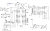
Looking at the code I have concerns that the LCD is using 4 bit code but not with the B ports in a row (B.0, B.1. B.2, B.3)
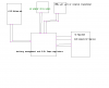
secondly the schematic shows LED resistors that calculate kinda hig for current but supposedly it works.
Just wish it utilized an 18F pic like a 1320.
Swordfish is sure easier to read.
If I can't get some sort of code then will go with the assenbly/hex file.
 
MrDeb you could write your own code using swordfish and 18f1320.
He is using the Lcd with 4 data lines he just using the lower portb pins for data
 
II thought you had to go in order B.0, B.1, B.2 etc.
I really would like to write my own code but where to start?
the SPI.bas I assume but how to use.
Was thinking of etching a pcb to solder the Max6675 to then have outputs for USART and go from there. The USART to see what is going on?
Use the SPI.bas, LCD.bas a little bit of code and maybe it might work.
The principle is (sounds) easy. The Max6675 outputs a compensated temp reading (ADC conversion) then have the LCD display results.
Using the Max6675 output data to control the on/off of the soldering iron via the opti coupler/triac.
any suggestions as this spi.bas is new to me as is pic programing in general.
I just got the grasp of using EAGLE.
 
general idea of prg flow

now just need to figure out the spi.bas and how to use it.
Thinking of etching a pcboard to mount the Max6675 as per requirements. The 1320 has no SPI port but the 452 does. Will this make things easier?
 

Attachments

  • block diagram.PNG
    block diagram.PNG
    22.2 KB · Views: 146
wrong diagram

hopefully this is right
 

Attachments

  • block of max6675.PNG
    block of max6675.PNG
    10.6 KB · Views: 162
Using the max6675 would be easy as pie. It dose all the work for you It's read only so it's just setting there wait to send out the temp
0*C is 00000000000 and 1024*C is 111111111111
 
schematic of proposed circuit

fairly easy layout
 

Attachments

  • temp soldering iron2.PNG
    temp soldering iron2.PNG
    41.1 KB · Views: 167
just read the bits. Is my idea of using a USART for testing of code viable?
This iron is fairly inexpensive compared to $75+ for ready built unit.
Tired of replacing tips due to being TOOO hot and wearing out (I understand the heat combined with the flux is what eats the tip away?
 
Status
Not open for further replies.

Latest threads

New Articles From Microcontroller Tips

Back
Top