Continue to Site

Welcome to our site!

Electro Tech is an online community (with over 170,000 members) who enjoy talking about and building electronic circuits, projects and gadgets. To participate you need to register. Registration is free. Click here to register now.

  • Welcome to our site! Electro Tech is an online community (with over 170,000 members) who enjoy talking about and building electronic circuits, projects and gadgets. To participate you need to register. Registration is free. Click here to register now.

Using a transistor as a switch

Status
Not open for further replies.

Mike18

New Member
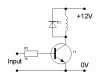
I'm working on a project for school where I need to build a computer controlled racetrack. My portion of the task is to design the light tree (the red, yellow, and green light sequence that runs prior to the starting of the race) and the starting gate. The light tree now works perfectly. When the green light goes on, the starting gate should open to allow the cars to begin racing. This is where my problem is. There is about 3.3V coming out of the light tree, but since we are using a typical computer power supply there is also a 12V source. I need to make this 3.3 volts trigger a 12V DC solenoid. The schematic I have so far is below:

**broken link removed**

The 3.3V supply is what is coming in from the light tree. The 12V is from the power supply. The 12ohm resistor (on the top) is where a relay will be that then connects to the solenoid. I don't know too much about transistors, so I haven't been able to debug this myself. Am I on the right track? How can this schematic be changed to accomplish what I'm trying to do?
Thanks in advance for your help.
 
Hi,

you have the transistor upside down. I can't draw a schematic right now, but you pretty much need to:

- Connect to +12 the upper node of D1-R1 (the one that is now to GND)
- Connect the emitter (the one with the arrow) of the transistor to ground
- Remove R3, after all you want to use the transistor as a switch so you don't need (want to) bias the base

You might need to tweak R2 value but I guess it's should be ok to saturate Q5 with that input voltage.
 
Thanks, those tips seem to get me along the right track, but it still isn't working like I'd hoped (probably my fault, but we'll see). Here's what I have now.

**broken link removed**

With this setup, by tweaking R1, I can only get a voltage across R3 to be around 2.2 volts. I need it to be 6V at minimum. Am I doing something wrong?

Thanks again
 
Mike18 said:
With this setup, by tweaking R1, I can only get a voltage across R3 to be around 2.2 volts. I need it to be 6V at minimum. Am I doing something wrong?

Yes, you are using the transistor in common collector mode, it needs to be common emitter. The circuit attached is what you need, the solenoid is in the collector, the diode across it prevents the transistor been destroyed by back EMF when it turns off.
 

Attachments

  • transistor_112.gif
    transistor_112.gif
    1.5 KB · Views: 366
Status
Not open for further replies.

New Articles From Microcontroller Tips

Back
Top