Continue to Site

Welcome to our site!

Electro Tech is an online community (with over 170,000 members) who enjoy talking about and building electronic circuits, projects and gadgets. To participate you need to register. Registration is free. Click here to register now.

  • Welcome to our site! Electro Tech is an online community (with over 170,000 members) who enjoy talking about and building electronic circuits, projects and gadgets. To participate you need to register. Registration is free. Click here to register now.

Using a Junebug to program another microcontroller

Status
Not open for further replies.
As long as you do not get a positive identification on the device ID not much else matters.
PKWarn0003: Unexpected device ID: Please verify that a PIC18F4685 is correctly installed in the application. (Expected ID = 0x2760, ID Read = 0x0)
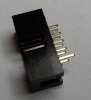
It suggested there is not a good connection in your ICSP wiring. It may well be that the header pins are not long enough, mine never were but they would catch just enough to let you think the were. Then check the wiring again.

Once you get that figured out you need a pullup on MCLR to force it high which allows the PIC to run.
 
Place a wire between pins +5V & U5V on the 16 pin header on the top of the Junebug, this will bypass the MOSFET & supply raw USB power to the target.
The 2x5 connectors pins might be too short to make good contact with the breadboard. There is a thread here somewhere about long pin extensions to a 2x5 header.

Your layout and clear photos look fine to me. It should work.
If you have a logic probe or scope try the 20kHz self test on PCG & PCD on the target.

PS if you leave DIP switch #1 on this will enable the internal pull-up resistor on MCLR handy in a pinch if you need it (not required for programming, just debugging)

PPS you can use the last 6 pins on the 16 pin header (ignore PGM) instead of the 2x5 connector. This connector is jumper wire friendly (and connects exactly like a PICKit2's 6 pin connector)
 
Last edited:
Is this correct?
263-5VtoU5V.jpg


I want to be sure I am doing this right, before powering the Junebug with this type of configuration.

In addition, the pins may in fact be too small like you guys are saying. I was hoping that it wouldn't be the problem as it took me a while to get the connectors. I'll do a search for that pin extension Blueroom mentioned.
 
Yes that's correct in the photo. In hindsight it's probably the pins are too short for the breadboard.
In a pinch you try pushing the pins down 0.1" or so in the header to see if that makes a difference.
 
Alright, I connected to it and I get:

Code:
Found PICkit 2 - Operating System Version 2.32.0
PICkit 2 Unit ID = Junebug
Target power detected ( 4.99V)
PKWarn0003: Unexpected device ID:  Please verify that a PIC18F4685 is correctly installed in the application.  (Expected ID = 0x2760, ID Read = 0x0)
PICkit 2 Ready

So, the program definitely recognizes the target power. However, I shaved off the little plastic dots (at the base of the connector) to try and buy myself an extra mm of pin length. But, even while applying a decent amount of pressure to the connector, I still get the same error as before when I go to program it. So, that means I most likely do need a pin extension.

EDIT: I am doing a bit of searching, but I can't seem to find a thread suggesting a specific connector for pin extensions. I had a bit of trouble getting the 10 pin IDC connector, so if anyone finds anything in particular I would appreciate it very much. Thanks.
 
Last edited:
What Bill is meaning is that you can pull (or push) the pins a Little so they make contact. In the attached picture I have pulled the corner pin out to illustrate.

Edit, I haven't tried this as I always solder on the headers.

Mike.
 

Attachments

  • socket.jpg
    socket.jpg
    55.4 KB · Views: 118
Last edited:
I tried to take the pins out one by one with a pair of pliers, unfortunately some of the pins snapped since they are somewhat brittle. I hope only having a single pin in some of the columns doesn't affect anything. I do have a backup 10pin IDC connector, but I don't want to start ripping some of its pins out just yet. Anyway, here are a few screens of what I set up:

264-pinimage1.jpg


265-pinimage2.jpg


(I also tried just putting the ribbon connector right on top of the pins so I wouldn't get the added width of the header).


Now, I think a I maybe having the reverse problem. The wire going into the bread board is long enough, but it isn't long enough for the ribbon cable connection. The pin length itself it just too small to satisfy both the bread board and the ribbon cable. I measured the pin length and it comes out to 1.2cm. The width of the header shaves off about 2.5mm. So I only have a little under 1 cm to play with. That's less than 5mm for the bread board and the ribbon cable Unless anyone can recommend an alternative, I think I am going to have to purchase and solder on a dual header as Promme's suggested.

Prommie if you don't mind, would you be able to link me to where you purchased that particular header? It would be a big help to me. Thank you.

EDIT:
I tried this method again with a bit shorter wires, but I still don't have any luck. The wires are longer and of about the same consistency as the pins, so I don't quite understand why it isn't working. Here's a few other pictures of what I tried:

266-pincomparison.jpg


267-pincomparison2.jpg


It still get the same error message in the output window, which fails to identify my PIC18F4685 microcontroller. I'm now wondering if it could be something else, but I am unsure of what that might be. I still may go ahead with the dual header method, but I am not so sure that the connections are the problem.


It Works!

It ended up being something really simple. One of the sides of the microcontroller was loose. I guess after all of the fiddling it became loose so I just popped it back in and it now works. Thank you all for your help I really appreciated it.

The picture above with the green wires is the current connection setup I am using (for anyone starting out like me).

Output window now displays:

Code:
Found PICkit 2 - Operating System Version 2.32.0
PICkit 2 Unit ID = Junebug
Target power detected ( 4.99V)
PIC18F4685 found (Rev 0x1)
PICkit 2 Ready

and

Code:
Programming Target (1/30/2010  3:25:42 AM)
PIC18F4685 found (Rev 0x1)
Erasing Target
Programming Program Memory (0x0 - 0xFF)
Verifying Program Memory (0x0 - 0xFF)
Programming Configuration Memory
Verifying Configuration Memory
PICkit 2 Ready
 
Last edited:
I'm in Australia and so my nearest stockist is **broken link removed**. If you fill in your location then someone may be able to suggest a local supplier.

One thing to check is that when it's connected (with the wires as in your last pic), meter between Con6 and your pic chip to see which of the 5 lines isn't connected.

Edit, congratulations.

Mike.
 
Last edited:
Alright, so now I am trying to blink a single LED with the microcontroller. I have a wire coming out of pin 4 (RA2) going to a resistor and then to a LED. The resistor is 100ohms and I am not reading any voltage across it.

316-ledtest1.jpg


319-pindiagramred.png


Here is my code:

Code:
#pragma config OSC=IRCIO67, WDT=OFF, LVP=OFF, DEBUG=ON
#include <p18f4685.h>
#include <delays.h>

void main()
{
ADCON1 = 0x0F; // make RA0 digital
TRISA = 0b00000000;
//PORTA = 0b00000100; // Turn LED on
LATA = 0b00000100;
while(1); // loop forever
}

318-correctornot.jpg

Is this correct?


I tried LATA and commented PORTA (as well as the other way around), I am unsure if I am using that command properly. But, from what I understand TRISA sets the pins to either input (value of 1) or output ( value of 0). Then select the pin you want to output to with a 1. I may not have the LED circuit wired correctly, but I should at least see a voltage across the resistor, no?
 
Last edited:
Try adding CMCON=0x07; to turn of the comparators (shouldn't matter for port A) and CVRCON=0; to turn off the voltage reference.

Mike.
 
Last edited:
I added the lines into the code as follows:

Code:
#pragma config OSC=IRCIO67, WDT=OFF, LVP=OFF, DEBUG=ON
#include <p18f4685.h>
#include <delays.h>

void main()
{
ADCON1 = 0x0F; // make RA0 digital
CMCON=0x07;
CVRCON=0;
TRISA = 0b00000000;
//PORTA = 0b00000100; // Turn LED on
LATA = 0b00000100;
while(1); // loop forever
}

Is this correct? I also have my oscilloscope measuring across the resistor. I do see a small bosunce in voltage when I hit program, but only for a slight second, and it barely pulls it up 25mV and it seem to be jittery. I'm not sure what could be the problem. However, I can confirm that I am getting 5V coming out of the ribbon cable and to the bread board from the green wires as shown before.
 
Last edited:
Alright, I figured out the problem. I had to set the all of the pins I wasn't using as inputs and ground them. However, when I connect to the Junebug the LED turns off. Only when I first plug in the Junebug, the LED lights up. When I connect or program I just see the LED flash.

340-ledtest2.jpg

(only turns on when first connected, else it just blinks when connecting or programming)

Code:
#pragma config OSC=IRCIO67, WDT=OFF, LVP=OFF, DEBUG=ON
#include <p18f4685.h>
#include <delays.h>

void main()
{
ADCON1 = 0x0F; // make RA0 digital

TRISA =   0b11111011;
//PORTA = 0b00000100; // Turn LED on
LATA = 0b00000100;

while(1); // loop forever
}


Does anyone know what I might be doing wrong? I would greatly appreciate the help. Thank you.

EDIT:

When I try to program it with the bits in PORTA or LATA as all zeros, the LED doesn't blink and doesn't light upon connecting the Junebug to my computer. So, the code is working to some extent. I also tried an infinite for loop to try an make the LED blink on and off, but it doesn't seem to work.

Code:
#pragma config OSC=IRCIO67, WDT=OFF, LVP=OFF, DEBUG=ON
#include <p18f4685.h>
#include <delays.h>

void main()
{
int x=1;
ADCON1 = 0x0F; // make RA0 digital

for(;;)
{
     for(x;x<=100;x++)
     {
     TRISA =   0b11111011;
     LATA = 0b00000100;
     }

     for(x;x>=1;x--)
     {
     TRISA =   0b11111011;
     LATA = 0b00000000;
     }
}

while(1); // loop forever
}


EDIT2:

I got it to work!

Code:
#pragma config OSC=IRCIO67, WDT=OFF, LVP=OFF, DEBUG=ON
#include <p18f4685.h>
#include <delays.h>

void main()
{
int x=1;
ADCON1 = 0x0F; // make RA0 digital

for(;;)
{
     for(x;x<=500;x++)
     {
     TRISA =   0b11111011;
     LATA = 0b00000100;
     }

     for(x;x>=1;x--)
     {
     TRISA =   0b11111011;
     LATA = 0b00000000;
     }
}

while(1); // loop forever

}

I had to make the for loop statement do a bit more work in order to see it blink. Also, the wires I have I believe are 22 gauge, my friend has 20 gauge wires so I can make it more stable. As it is now I have to "jiggle" the wires a bit every so often, becasue they come loose. So, the connection is a bit flimsy, but I should be correctable with some thicker wires.


In addition, the program only runs upon reconnecting the Junebug to my computer. Launching MPLAB 8 and connecting and programming it simply make the LED flash once no matter the code. This indicates that it worked, but again, the program will not run until replugged back into the computer.
 
Last edited:
Alright, I figured out the problem. I had to set the all of the pins I wasn't using as inputs and ground them. However, when I connect to the Junebug the LED turns off. Only when I first plug in the Junebug, the LED lights up. When I connect or program I just see the LED flash.

340-ledtest2.jpg

(only turns on when first connected, else it just blinks when connecting or programming)

Code:
#pragma config OSC=IRCIO67, WDT=OFF, LVP=OFF, DEBUG=ON
#include <p18f4685.h>
#include <delays.h>

void main()
{
ADCON1 = 0x0F; // make RA0 digital

TRISA =   0b11111011;
//PORTA = 0b00000100; // Turn LED on
LATA = 0b00000100;

while(1); // loop forever
}


Does anyone know what I might be doing wrong? I would greatly appreciate the help. Thank you.


Why isnt anyone helping? This code will turn on a LED ONLY. You want to blink ? You have to turn it off then delay then on then delay etc.... Also you arent telling the PIC what speed to run at...

Try this:

Code:
void main()
{
	OSCCON = 0x72; 				//8MHz clock
	while(!OSCCONbits.IOFS); 	//wait for osc stable

	ADCON1 = 0x0F; 				// make RA0 digital
	TRISA =   0b00000000; 		//You can leave all outputs.. (Recommended)

	while(1){ 					// loop forever
		LATA = 0b00000100;		//ON
		Delay10KTCYx(100);		//DELAY 500mS
		LATA = 0b00000000;		//OFF
		Delay10KTCYx(100);		//DELAY 500mS
	}
}
 
Last edited:
Coding like this can also help...
Code:
#pragma config OSC=IRCIO67, WDT=OFF, LVP=OFF, DEBUG=ON
#include <p18f4685.h>
#include <delays.h>

#define Delay500mS() Delay10KTCYx(100)
#define LED LATAbits.LATA2
#define ON 1
#define OFF 0

void main()
{
	OSCCON = 0x72; 				//8MHz clock
        while(!OSCCONbits.IOFS); 	//wait for osc stable

	ADCON1 = 0x0F; 				// make RA0 digital
	TRISA =   0b00000000; 		//You can leave all outputs.. (Recommended)

	while(1){ 					// loop forever
		LED = ON;				//ON
		Delay500mS();				//DELAY 500mS
		LED = OFF;				//OFF
		Delay500mS();				//DELAY 500mS
	}
}

https://www.youtube.com/watch?v=5u3gLIOkk-s
 
Last edited:
Ok this isnt good:
Code:
#pragma config OSC=IRCIO67, WDT=OFF, LVP=OFF, DEBUG=ON
#include <p18f4685.h>
#include <delays.h>

void main()
{
int x=1;
ADCON1 = 0x0F; // make RA0 digital

for(;;)
{
     for(x;x<=500;x++)
     {
     TRISA =   0b11111011;
     LATA = 0b00000100;
     }

     for(x;x>=1;x--)
     {
     TRISA =   0b11111011;
     LATA = 0b00000000;
     }
}

while(1); // loop forever

}

but this might be ok:
Code:
#pragma config OSC=IRCIO67, WDT=OFF, LVP=OFF, DEBUG=ON
#include <p18f4685.h>
#include <delays.h>

void main()
{
    unsigned int x;

    OSCCON = 0x72;                //8MHz clock
    while(!OSCCONbits.IOFS);      //wait for osc stable

    ADCON1 = 0x0F;                // make RA0 digital
    TRISA =   0b00000000;         // make all output

for(;;)				  // main loop
{
     for(x=0;x<1000000;x++)
     {
         LATA = 0b00000100;	  // turn on 1,000,000 times (aka 500mS)
     }

     for(x=0;x<1000000;x++)
     {
         LATA = 0b00000000;	  // turn off 1,000,000 times (aka 500mS)
     }
}


}
 
Last edited:
I thank you for your help. The main problem above was just getting the LED to turn on. Initially, I was just trying to turn the LED on, as you said yourself. However, it would only flash once while reconnecting to the junebug or programming. This would happen regardless if I was trying to make it blink or not (with or without the for loops). In order for the program to actually run I have to physically disconnect the junebug from my PC and reconnect it's USB cable. The code I have above:

Code:
#pragma config OSC=IRCIO67, WDT=OFF, LVP=OFF, DEBUG=ON
#include <p18f4685.h>
#include <delays.h>

void main()
{
int x=1;
ADCON1 = 0x0F; // make RA0 digital

for(;;)
{
     for(x;x<=500;x++)
     {
     TRISA =   0b11111011;
     LATA = 0b00000100;
     }

     for(x;x>=1;x--)
     {
     TRISA =   0b11111011;
     LATA = 0b00000000;
     }
}

while(1); // loop forever

}

This does work and does blink at about 50-100ms intervals. Increasing this to 15,000 seems to be about 500ms.


The two lines:

Code:
    OSCCON = 0x72;                //8MHz clock
    while(!OSCCONbits.IOFS);      //wait for osc stable

I don't understand why, but these line don't seem to affect the code in anyway. But, I do appreciate the input. I realize now that I don't need the while loop at the end as well as the TRISA calls within the for loops. I modified your code so mine looks a bit neater and accurate. I also changed the for loops back as well.


Code:
#pragma config OSC=IRCIO67, WDT=OFF, LVP=OFF, DEBUG=ON
#include <p18f4685.h>
#include <delays.h>

void main()
{
    unsigned int x=0;

    OSCCON = 0x72;                //8MHz clock
    while(!OSCCONbits.IOFS);      //wait for osc stable

    ADCON1 = 0x0F;                // make RA0 digital
    TRISA =   0b11111011;         // make all input but RA2 (pin 4)

for(;;)				  // main loop
{
     for(x;x<=15000;x++)
     {
         LATA = 0b00000100;	 
     }

     for(x;x>=1;x--)
     {
         LATA = 0b00000000;	  
     }
}

}

Again, thank you for the response, for this has helped me.

EDIT
I figured out how these lines affect the code and timing.

Code:
    OSCCON = 0x72;                //8MHz clock
    while(!OSCCONbits.IOFS);      //wait for osc stable

This increased the rate at which the LEDs blink. Before, with the for loop set at 500 it would blink at the rate it does now(with the two lines added into the code) set at 15000. I'm not sure why this is, since I thought the operating frequency of the microcontroller was 8MHz to begin with. So, I guess it is better to specify 8Mhz, so I'll keep it in for insurance.
 
Last edited:
Status
Not open for further replies.

Latest threads

New Articles From Microcontroller Tips

Back
Top