Continue to Site

Welcome to our site!

Electro Tech is an online community (with over 170,000 members) who enjoy talking about and building electronic circuits, projects and gadgets. To participate you need to register. Registration is free. Click here to register now.

  • Welcome to our site! Electro Tech is an online community (with over 170,000 members) who enjoy talking about and building electronic circuits, projects and gadgets. To participate you need to register. Registration is free. Click here to register now.

Using a Junebug to program another microcontroller

Status
Not open for further replies.

micro9000

New Member
Hey guys, this is my first time posting here. It was recommended by the all about circuits forum that I post my questions here. I apologize if this has been asked before, but I could use the help specifically related to my problem. I've started to try and program my microcontroller using the Junebug which I have purchased. I have the PIC18F4685, and I was wondering how I go about programming it through the Junebug.

I have built and compiled a successful program for the Junebug where the LEDs flash. In doing so, I have made sure that the link and library paths are correctly linked in build options. Also, I have the necessary header file for the PIC18F1320, which the Junebug uses.

I have found this C program on a tutorial site to do a simple test. Here is the code I have used:

Code:
#pragma config OSC=INTIO2, WDT=OFF, LVP=OFF, DEBUG=ON
#include <p18f1320.h>
#include <delays.h>

void main()
{
ADCON1 = 0x7F; // make RA0 digital
TRISA = 0b10111110;
PORTA = 0b00000001; // Turn LED on
while(1); // loop forever
}
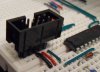
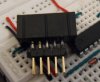
Now, here is the problem. When I connect the ribbon cable shown here (the second picture towards the bottom):

16F or 18F and advice on selecting a programmer to use - Page 2 - All About Circuits Forum

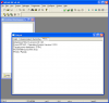
I get the following error:

Code:
Programming Target (12/18/2009  12:55:25 AM)
PKWarn0003: Unexpected device ID:  Please verify that a PIC18F1320 is correctly installed in the application.  (Expected ID = 0x7C0, ID Read = 0x0)
Erasing Target
Programming Program Memory (0x0 - 0xF7)
Verifying Program Memory (0x0 - 0xF7)
PK2Error0027:  Failed verify (Address = 0x0 - Expected Value 0xEF63 - Value Read 0xFFFF)
PICkit 2 Ready
(Note: This only occurs when I connect the ribbon cable to the Junebug)

I realize I am most likely missing a lot of steps and I probably should call to the PIC18F4685
header file, but I am unsure of what else I could be doing wrong or how to even go about making the Junebug program the other PIC.


In sum
______________
What do I need to add to the code (I'm sure it's off by a lot) or modify physically to properly program the PIC18F4685 using the Junebug?

As always your help is much appreciated. Thanks in advance.

EDIT
____
I do not currently plan to flash LEDs with the other PIC, but if possible, simply read any voltages/square waveforms coming out of one of the pins using my oscilloscope.
 
Last edited by a moderator:
Looks like the programming software is asking the PIC, through the Junebug, for its ID before it continues to program the chip. It is getting 0, but was expecting 7C0 hex. Like the Junebug can not talk to the PIC.

So check the power hookup, connectors, make sure the chip in right and no bent pins. I would guess the PC is talking to the junebug since you are not seeing a communication error.

Sure other here can offer more details. I like those blue boards.
 
Make sure all the dip switches on the junebug are set to off when programming an external PIC. Also all VDD & VSS pins must be connected on the target pic to power & gnd respectivly.
Tip use the standalone PICkit2 software as it'll do autodetect on many pics.
 
I tried compiling it with the 3 pins down and without connecting the ribbon cable and it fails to work. The build succeeds, but when I go "programmer/program" I get the following error message:

Code:
Programming Target (12/29/2009  6:20:15 PM)
PKWarn0003: Unexpected device ID:  Please verify that a PIC18F1320 is correctly installed in the application.  (Expected ID = 0x7C0, ID Read = 0x0)
Erasing Target
Programming Program Memory (0x0 - 0xF7)
Verifying Program Memory (0x0 - 0xF7)
PK2Error0027:  Failed verify (Address = 0x0 - Expected Value 0xEF63 - Value Read 0x0)
PICkit 2 Ready

Note- this occurs with and without the ribbon cable attached and the all the white switches are down.

Now I also edited the code to have two include statements calling to the Junebug and the 18F4685. But, this just results in a failed build.

Also, Blueroom, I am thankful for your response, but I am still lost by what you mean by stand alone PICkit 2 software. Can you please tell me where or how to install this necessary software. Thanks again.

EDIT:
_______________
I rechecked the connections and just to make sure:

**broken link removed**

-I have the VPP going from the ribbon cable to pin 1.
-GND from the ribbon cable going to pins 12 and 31 (VSS)
-The +5V to pins 11 and 32 (VDD)
-PGD pin 40
-PGC pin 39

I have rechecked to make sure they are going to the proper pins. Note all wires are connected to the ribbon cable and are not coming from any other source.
 
Last edited:
Describing switches as down does not help as we have no idea which way your Junebug is orientated. To program the 18F1320 that is part of the Junebug the switches should be on, to program a chip connected to the ribbon cable they should be off. On is toward the ribbon cable.

Mike.
 
Yes, I am aware of how the switches should be oriented from the posts above. I have them in the off position. I'll post a picture so it's a bit more clear. But, it doesn't work either way. How would you set the program up if you wanted to program for the other microcontroller? Right now the device I have selected is the one on the junebug(configure/select device and I have selected the 18f1320). If I select another device, mainly mine (18f4685) and inlcude another header file, the compiler does not recognize the junebug and I receive errors.

Basically, what are the necessary changes I have to make to the program or compiler in order to program the other microcontroller? Blueroom mentioned standalone pickit 2 software, which I don't quite understand how to obtain or install. If someone could point me in the right direction that would be much appreciated. Thanks again.

Edit
_____________

Here is a picture of the switches:

**broken link removed**

Here is another picture of the wiring (don't pay any attention to that resistor at the moment):

**broken link removed**

Also it may not look like it from that angle, but the wires are not touching each other creating a short.
 
Last edited:
Removed as when I edited this post the post below appeared.

Mike.
 

Attachments

  • IDC1.jpg
    IDC1.jpg
    59.2 KB · Views: 715
  • IDC2.jpg
    IDC2.jpg
    60.1 KB · Views: 709
Last edited:
If you have the switches off then I suspect your connections aren't sufficient. On the other forum the picture showed wires stuck into an IDC connector. This will be very unreliable and probably not workable. The way I connect to a breadboard is with an IDC socket soldered to a dual header - see below.
**broken link removed** **broken link removed**

Mike.
 
That could be it, and thanks for the advice. If you don't mind me asking, what's a good and reliable site to get one of those?

However, let's assume the connections are sufficient. What do I need to change to the compiler or program, so I do not receive any errors? From your experience did you have to add in the other microcontrollers header file, and selected a different device? I am a bit confused as how to set up the compiler and program template, so I may program the other microcontroller, and not the junebug's 18F1320.
 
Last edited:
The socket pictured above is the same one that is in the Junebug with a header soldered on. Once it is connected properly selecting Pickit2 and the right device should find it. Attached is what I see when I am connecting to a 16F886.

Edit, for clarity I've attached a picture of the two parts that are soldered together.

Mike.
 

Attachments

  • MPLAB.png
    MPLAB.png
    40.3 KB · Views: 232
  • header.jpg
    header.jpg
    37.6 KB · Views: 207
Last edited:
What include file do you have for the program? Right now mine is:

Code:
#include <p18f1320.h>

Should it be the microcontoller I plan to program? For example:

Code:
#include <p18f4685.h>

In addition, you have the junebug's microcontroller selected as a device (configure/ select device and I have the 18f1320 selected), correct? I thank you so much for your already great advice and responses.

EDIT:
_____________

I failed to mention that the yellow light turns on when the switches are "off." When I turn the first three switches back to the on position, the yellow light goes away and I can successfully program to the junebug. When the switches are off, it fails to recognize the junebug period. What could be the problem here? Is it that the wiring I have set up is insufficient, like you said?

**broken link removed**

The yellow light turns on when starting it up, but then it goes away after attempting to connect to the junebug whether it is successful or not. Just out of curiosity what does this yellow light indicate?
 
Last edited:
If you have the switches off then I suspect your connections aren't sufficient. On the other forum the picture showed wires stuck into an IDC connector. This will be very unreliable and probably not workable. The way I connect to a breadboard is with an IDC socket soldered to a dual header - see below.
Mike.
Ah, another convert I see. :D Hi Mike.
 
You include the file for the target processor. So, if you are using the tutor (switches on) then you include p18f1320.h. If you are programming a 18F4685 then you include p18f4685.h and select it as the device under configure->select device.

Mike.
 
Alright, I modified the one line in the following code:

Code:
#pragma config OSC=INTIO2, WDT=OFF, LVP=OFF, DEBUG=ON
[B]#include <p18f4685.h>[/B]
#include <delays.h>

void main()
{
ADCON1 = 0x7F; // make RA0 digital
TRISA = 0b10111110;
PORTA = 0b00000001; // Turn LED on
while(1); // loop forever
}

I am unable to successfully build the code, and I receive this error:

Code:
Executing: "C:\MCC18\bin\mcc18.exe" -p=18F4685 /i"C:\MCC18\h" -I"C:\MCC18\bin\LKR" "codetest.c" -fo="codetest.o" -D__DEBUG -Ou- -Ot- -Ob- -Op- -Or- -Od- -Opa-
C:\Users\XMACHINE9000\Desktop\testproject C\codetest.c:1:Error [1225] configuration value 'INTIO2' not recognized for configuration setting 'OSC'
Halting build on first failure as requested.
----------------------------------------------------------------------
Debug build of project `C:\Users\XMACHINE9000\Desktop\testproject C\code2.mcp' failed.
Language tool versions: mpasmwin.exe v5.34, mplink.exe v4.34, mcc18.exe v3.34
Preprocessor symbol `__DEBUG' is defined.
Wed Dec 30 03:07:21 2009
----------------------------------------------------------------------
BUILD FAILED


And, when I try connecting (program->connect) I get:

Code:
Found PICkit 2 - Operating System Version 2.32.0
PICkit 2 Unit ID = Junebug
Target power not detected - Powering from PICkit 2 ( 5.00V)
PKWarn0003: Unexpected device ID:  Please verify that a PIC18F4685 is correctly installed in the application.  (Expected ID = 0x2760, ID Read = 0x0)
PICkit 2 Ready

I am guessing the connections are insufficient like you said, but why is the build not succeeding. At the very least it should still be able to build properly, no?

EDIT:

I tried commenting the code within main and it still fails to build, so the error must be within the first line of the code outside of main.

Code:
 #pragma config[B] OSC=INTIO2[/B], WDT=OFF, LVP=OFF, DEBUG=ON
According to the error message, the part of the code in that line causing the error is OSC=INTIO2
 
Last edited:
The config needs changing,
Code:
#pragma config OSC=[COLOR="red"]IRCIO67[/COLOR], WDT=OFF, LVP=OFF, DEBUG=ON
#include <p18f4685.h>
#include <delays.h>

void main()
{
ADCON1 = 0x7F; // make RA0 digital
TRISA = 0b10111110;
PORTA = 0b00000001; // Turn LED on
while(1); // loop forever
}

Mike.
 
Thank you very much for the help, the build is now successful. I am sorry for the plethora of questions, but what does part in that particular line of code mean? Anyhow, I will go ahead and see if I can purchase one of those 10 pin IDC as you suggested. Now that I know I have the compiler and program set up properly I can go ahead and troubleshoot the connections. Thanks again.
 
Last edited:
The bits of the line mean,
OSC=IRCIO67 is internal RC oscillator with I/O on 6&7
WDT=OFF is WatchDog Timer off
LVP=OFF is Low voltage Programming off
DEBUG=ON is, go on, guess.

Mike.
 
ADCON1 has the 2 most significant bits un writable..dont think that it will cause a problem but it is not a good practice.For all digital write 0x0F;(whats on the other two bits does not matter since you do not use the AD module but this is necessary to maintain a constant level of understanding one might get confused).Page 250 of datasheet
No need to include delays.h since you are not using it.
Inorder to output to any port use LATx etc and not PORT A(page 131 of data sheet).

From what you are doing i would advise you to go through 3V0's tutorials.
Untitled Document

They are simple and will help you out with C18.
 
Last edited:
Alright I managed to get an IDC 10 pin socket connector for my bread board:

261-10pinIDC2.jpg


262-10pinIDC1.jpg


When I try to connect to it (programmer->connect) I receive the following lines in the output window:

Code:
Found PICkit 2 - Operating System Version 2.32.0
PICkit 2 Unit ID = Junebug
Target power not detected - Powering from PICkit 2 ( 5.00V)
PKWarn0003: Unexpected device ID:  Please verify that a PIC18F4685 is correctly installed in the application.  (Expected ID = 0x2760, ID Read = 0x0)
PICkit 2 Ready

And, when I try to program it (programmer->program), the following displays in the output window:

Code:
Programming Target (1/29/2010  8:43:58 PM)
PKWarn0003: Unexpected device ID:  Please verify that a PIC18F4685 is correctly installed in the application.  (Expected ID = 0x2760, ID Read = 0x0)
Erasing Target
Programming Program Memory (0x0 - 0xFF)
Verifying Program Memory (0x0 - 0xFF)
PK2Error0027:  Failed verify (Address = 0x0 - Expected Value 0xEF63 - Value Read 0x0)
PICkit 2 Ready

I didn't solder the dual header as Pommie recommended, as I thought it wasn't necessary. Could this very well be a necessary addition?

If anyone can help me, it would be much appreciated, as I really want to start coding for my selected microcontroller. As always, thanks in advance.
 
Last edited:
Status
Not open for further replies.

New Articles From Microcontroller Tips

Back
Top