Continue to Site

Welcome to our site!

Electro Tech is an online community (with over 170,000 members) who enjoy talking about and building electronic circuits, projects and gadgets. To participate you need to register. Registration is free. Click here to register now.

  • Welcome to our site! Electro Tech is an online community (with over 170,000 members) who enjoy talking about and building electronic circuits, projects and gadgets. To participate you need to register. Registration is free. Click here to register now.

Using a 558 quad-timer package?

What's the best way to do this?

  • The 558 should be able to work for this

    Votes: 0 0.0%
  • You're better off with a 556 and a 555

    Votes: 0 0.0%
  • Heh... good luck.

    Votes: 0 0.0%

  • Total voters
    0
  • Poll closed .
Status
Not open for further replies.
Is anyone here familiar with the 558 (quad-timer -- mostly like four 555 timers in a single 16-pin DIP package)? I have a series of questions relating to it

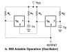
What I actually need are two monostable timers and an astable, in as small a footprint as possible. Since the 558 is compressed into a 16-pin package, the discharge and threshold pins of each timer (pins 7 and 6, respectively) are tied together. This is fine for the monostable timers I need, but prevents me from using one of the timers as an astable. Instead, the datasheet mentions that two of the timers can be tied together for astable operation, as per the diagram attached below.

Ultimately, I want the first monostable to act as a "delay" timer for the second (basically, the second monostable fires when the first monostable shuts off). I then want the second monostable to trigger the astable, acting as a duration timer, so the astable's output oscillates during the second monostable's pulse. Does it look like this can be accomplished with a single 558? If so, would i need any additional hardware besides the requisite resistors and capacitors? I've also attached an image of the signals to hopefully give a better idea of what I'm looking for.

Or would I just be better off using a 556 for the monostables and a 555 for the astable?

I only have a small area to work in, it must fit in an enclosure that's a little over 2"x2"x¾". Can anyone provide me with any pointers? Thanks!
 

Attachments

  • NE558-astable.png
    NE558-astable.png
    23 KB · Views: 1,282
  • waveform.gif
    waveform.gif
    1.2 KB · Views: 626
Last edited:
Using a 558 quad-timer package
Can you still buy that?
I would use a RC timer for the 1st part and then a 556 for the rest.
 
Last edited:
You can even connect the 558 as four independent astable timers (I've done it) but it requires additional capacitors and resistors and is subject to timing variability due to supply voltage fluctuation. You should be able to build the two-timer astable configuration as you propose.
 
My concern about the astable configuration suggested by the datasheet is that there doesn't seem to be an external trigger, and thus it would just constantly run as long as power is applied. Could I cheat by using the output of the monostable as the "Vcc" for the external components shown in the astable diagram there, so Vcc only exists while the monostable is outputting high?
 
If you can't configure the 558 as you want you could do all the timing instead with a single CD4093 quad NAND, as per the attached.
 

Attachments

  • GatedOsc.gif
    GatedOsc.gif
    22.2 KB · Views: 1,090
  • Gated Osc.asc
    2.7 KB · Views: 375
Hmmm, that's a very intriguing proposition, and looks like it just might do what I'm looking for. Will larger resistor/capacitor values give me longer delays? I'm looking for delay and duration times on the scale of 1-10 seconds, with an oscillation frequency of 1-20Hz (if changing the resistor and capacitor values does indeed alter the timings, then slapping a variable resistor in at the appropriate points should allow for the desired fine tuning, correct?).

My favorite online parts shops sell them for < 50¢ each, so that would be a cheaper solution, too!
 
Last edited:
My concern about the astable configuration suggested by the datasheet is that there doesn't seem to be an external trigger, and thus it would just constantly run as long as power is applied. Could I cheat by using the output of the monostable as the "Vcc" for the external components shown in the astable diagram there, so Vcc only exists while the monostable is outputting high?
I'm not sure what you mean by external components but you can use the output of the second monostable to control an "enable" device such as a transistor on the output of the astable while it's running continuously. Of course this method costs you a junction drop.
 
I'm not sure what you mean by external components but you can use the output of the second monostable to control an "enable" device such as a transistor on the output of the astable while it's running continuously. Of course this method costs you a junction drop.

(Yet another) good idea! The junction drop just means I have to recalculate the resistors for the little LED that this whole thing is powering. That brings up another question though... is the output of the 558 going to be Vcc, or will there be a junction drop involved? The whole thing's going to be powered on 4.5V, and if I have too many drops, I'll wind up with < 3V which wouldn't be very happy for a blue or white LED.

It's actually going in a friend's art project... but he wanted light and sound stuff so he came to me. I found a motion sensor device on eBay that will do 90% of what he wants (though I'll be dismantling it and tweaking a few things), but he wants this delayed flashing LED to go off when the motion sensor is triggered, and so I've embarked on this project.
 
For extended delay and duration periods (~ 1-10S) my earlier circuit isn't ideal but this modified circuit should do the trick.
R2 and C2 set the delay between a trigger pulse and oscillator startup.
R1 and C1 set the oscillator-active duration.
R3 and C3 set the oscillator frequency (~22Hz for the component values used in the simulation).

The CD4093 is readily available in SMD form if space is at a premium.

Edit: The four gates U1-U4 are all contained in a single CD4093B IC
 

Attachments

  • GatedOsc3.gif
    GatedOsc3.gif
    26.2 KB · Views: 929
  • GatedOsc3.asc
    2.9 KB · Views: 322
Last edited:
(Yet another) good idea! The junction drop just means I have to recalculate the resistors for the little LED that this whole thing is powering. That brings up another question though... is the output of the 558 going to be Vcc, or will there be a junction drop involved? The whole thing's going to be powered on 4.5V, and if I have too many drops, I'll wind up with < 3V which wouldn't be very happy for a blue or white LED.

You may be able to add a transistor or gate as an enable line on the trigger of your first astable timer to preserve maximum output voltage but I haven't tried it.
 
For extended delay and duration periods (~ 1-10S) my earlier circuit isn't ideal but this modified circuit should do the trick.
R2 and C2 set the delay between a trigger pulse and oscillator startup.
R1 and C1 set the oscillator-active duration.
R3 and C3 set the oscillator frequency (~22Hz for the component values used in the simulation).

For a slower oscillation frequency, would a larger cap as C3 (like 1µF) do the trick? Along with a 500KΩ variable resistor as R3 (plus a 47KΩ in series), shouldn't that give me a range of about 1.83Hz-21.28Hz? I'm guessing this based on the RC time constant anyways -- let me know if I'm not understanding this correctly?
 
Yes, 1uF/500k/47k should be fine. The simulation gives a range of 2.8Hz-32.6Hz with those values and a 4.5V supply.
This type of oscillator is very reliable with a wide range of RC values.
 
Well I ended up creating this circuit using a 556 and 555, with three trimpots. It worked great until I shipped the board, at which point the third trimpot broke internally, so now it's on its way back to me to have the trimpot replaced >_<

BTW, the entire board measured in at 1.55" x 1.5" ... I'm fairly proud of myself for squeezing it all into that, and I'm glad I did, because when I tried fitting the board into his art piece, it barely fit at that size :eek:
 
Status
Not open for further replies.

Latest threads

New Articles From Microcontroller Tips

Back
Top