Continue to Site

Welcome to our site!

Electro Tech is an online community (with over 170,000 members) who enjoy talking about and building electronic circuits, projects and gadgets. To participate you need to register. Registration is free. Click here to register now.

  • Welcome to our site! Electro Tech is an online community (with over 170,000 members) who enjoy talking about and building electronic circuits, projects and gadgets. To participate you need to register. Registration is free. Click here to register now.

Use of AD835 Multiplier IC to Modulate Sub Audio Signal

Status
Not open for further replies.

pnielsen

Member
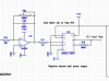
The attached schematic is intended to multiply a 1Vpp sub audio (ELF) frequency with a slow randomly changing, arbitrary waveform from the LM324 stage. The objective is to have the sub audio signal vary in both phase and amplitude in response to the random signal.

Can anyone please tell me if I am using the AD835 IC correctly?

Will the IC operate correctly at these low frequencies?

How can I adjust the modulation depth? Is it done by proportioning the relative voltages of the two signals?
 

Attachments

  • modulator.png
    modulator.png
    13.2 KB · Views: 494
Do I need to provide additional information? Before I order the AD835 (not cheap getting it here), I would like to know if the approach shown in my schematic will work.
 
The principle and levels look OK, from the data sheet, but the connections appear swapped over, unless it's just the text?

X and Y are the inputs and W output, but W is shown as input on the drawing?

Also, it appears Z should be grounded if you do not need the extra summing input.
(Page 10 if the data sheet, Basic operation: "with X = X1 − X2, Y = Y1 − Y2, and Z = 0").
 
Below is an LTspice simulation of your circuit as best I understand.
I only had a model for the AD633 so I used that.
(It's cheaper than the AD835 and works on +/- 15V)

Summing Input Z should be grounded when using the device as a multiplier..
I don't know why you had it connected to W through a resistor.

Yes, the circuit operates down to DC.

Yes, you adjust the modulation depth by the relative amplitude of the two signals.

The simulation is shown with two arbitrary input signals, a sinewave ELF (red trace) and a low-frequency random modulating signal (blue and green trace) .
I increased the value of the ELF signal to get a reasonable output voltage (yellow trace).
Is that the type of output you expect?

1572073676881.png
 
Last edited:
Thanks for the two replies. Good thing I checked here. The output shown by crutschow is exactly what I am looking for.

If I may ask, why did you tie X1 to ground and not X2 as shown in the AD datasheet?

Also, according to the data sheet, the AD835 will only take max +/-5VDC rails. I did not choose the AD633 because someone elsewhere said it would not handle ELF's. But seeing that it works in the sim, I will use it instead so I can operate it from the same +/-15VDC supply as the rest of the circuit. It is a lot cheaper as well.

Brilliant. Thanks so much.
 
f I may ask, why did you tie X1 to ground and not X2 as shown in the AD datasheet?
Because that's the way you had it connected in your schematic.
Since the inputs are differential, all that does is invert the phase of the signal by 180 degrees.
Either input can be grounded (or both can be used with a differential signal).

In this case it makes the ELF signal in phase with the Ran signal since the op amp circuit also inverts the signal by 180 degrees (but that's not likely a factor in your application).
I did not choose the AD633 because someone elsewhere said it would not handle ELF's.
Don't know why "someone elsewhere" would say that. (?)
They both are similar devices.
I think the main difference (besides max supply voltages) is the AD835 has a higher frequency response, which is not a factor in your low frequency application.
 
Thank you for clarifying those points.

BTW I like the way you divided the white noise by 30 in LTSpice to obtain the slow randomwave. Didn't know that could be done.
 
I like the way you divided the white noise by 30 in LTSpice to obtain the slow randomwave. Didn't know that could be done.
Yes, typically the variable is time multiplied by some value to get a higher frequency white noise, but you obviously can divide it by a number to get a low frequency.
 
Status
Not open for further replies.

Latest threads

New Articles From Microcontroller Tips

Back
Top