Continue to Site

Welcome to our site!

Electro Tech is an online community (with over 170,000 members) who enjoy talking about and building electronic circuits, projects and gadgets. To participate you need to register. Registration is free. Click here to register now.

  • Welcome to our site! Electro Tech is an online community (with over 170,000 members) who enjoy talking about and building electronic circuits, projects and gadgets. To participate you need to register. Registration is free. Click here to register now.

Usb1.1 conversion project

Status
Not open for further replies.

BlueDragon Audio

New Member
Hello everybody, I am working on a upgrade project, I have a peripheral that is implementing usb1.1, The problem is, is that this device is for high definition audio and 12mbps is just not cutting it ( Plus this controller is way outdated!) . I was wondering if anybody had any ideas on how I could mod this thing to where I could take advantage of 1394 or 2.0, I rather convert it using 2.0 because I would not have to change out the hub/interconnect. But if 1394 would be just as easy to do implement as the 2.0 I would have to go with 1394. I Know that I might have to change a few things around like the master clock and some other things, The current controller is a TUSB 3200c manufactured by Texas Instrument Inc, **broken link removed**, I need whatever controller(s) I am going to be using to do what the current streaming controller is doing but just alot faster. I know I am going to have some Issues with the Pin package, because the 3200c is a 52pin package and they don't make any new style controllers with that kinda layout.... But thats fine, I will find a way to connect it probably using a custom adapter.... anyways, any ideas would be awsome!

Thanks!!

Benjamin Sorenson
 

Attachments

  • SDC10471.jpg
    SDC10471.jpg
    2.7 MB · Views: 388
  • SDC10470.JPG
    SDC10470.JPG
    3.3 MB · Views: 311
I thought USB1.1 was low speed only or 1.5 MHz. -- no matter. If your USB1.1 device is running at 12 MHz. aka Full Speed and you wish to go to High Speed or 480 MHz. then I can confidently predict that you have absolutely no chance to modify an existing board for that purpose. You need to start from scratch, regardless of which way you go, to get where you think you need to be. What are you aiming at; 24/96 or 32/384?

While you're at it why not go for USB3.0 it has raised the price of poker substantially. It's your move check, call, or raise.

USB.org - Welcome

I'll get back to you with the USB Streaming Audio Chip we are using.
Edit: It is a TE7022L
 
Last edited:
Yea, I was looking @ the usb 3.0 controllers but I coulnt really find any that would be really good for peripheral use, there mostly for master controllers... Besides I rather Implement a controller that everybody can take advantage of, why use 3.0 if the majority of the public has 2.0 controllers installed on there motherboard? And Either way, 5gps is probably overkill for what I'm using. My Usb 1.1 controller is running on a 6mhz master clock,( Take a look at the clock, on the pic ) If you take a look @ the usb 2.0 controllers they all or mostly run off a a 6mhz clock as well, (The controllers from T.i) so there should be no issue with that. I am aiming for 24/96 or 1bit (Delta if possible) but it's not I don't think..... There should be no reason why I have to start from scratch because all my other A/D D/A converters can both run up to 212mhz or 1.0 bit delta.


It's not any of the sub components that are any issue because the devices installed are
capable of so much more....

480Mhz??
Here is a list of some common master clock freq.....

(32) 8.192 16.384
(44.1) 11.2896 22.5792
(48) 12.288 24.576
(64) 8.192 16.384
(88.2) 11.2896 22.5792
(96) 12.288 24.576
(176.4) 11.2896 22.5792
(192) 12.288 24.576
for example.....
CS5381
 
Just looking at clock frequencies can be deceptive. On USB 2.0, if there is a 6 MHz crystal/oscillator then there must be a PLL to boost that to 12 MHz. because that is one of only three bit rates used in USB 2.0 The others of course are 1.5 MHz. and 480 MHz. These are the data rates on the USB channel only. They are not related to the audio data rates at all. The ability to stream requires that the data arrive on the USB channel faster than it goes out on the audio channel, or that you have sufficient buffering to allow the USB channel to run behind the audio channel, but catch up in the gaps. It is still unlikely that you can upgrade a USB 1.1 board to work at 12 MHz. if it won't do that already, and no chance to make it work at 480 MHz.

On our USB chip we use a 12 MHz. CVXO and our audio processing chain starts with much higher frequencies than any that you mentioned, so I'm pretty confident that 12 MHz. is more than suitable for streaming audio.
 
Last edited:
hmmmm,,,,, ok, so if i were to start over here what kind of usb controller should I use for streaming audio from the phy to the cpu? Is there any particular controller that works best for this type of application?
 
ok, ok I think I get what your saying now about the usb1.1 controller, Hmm. I'm kind of a newb at this so forgive me for being so unaware.... So what your saying is that since my board was based off a usb 1.1 controller, There is a 0% chance of me removing the old controller and replacing it with a high speed controller because....The traces from the usb controller to to the phy would have to be changed??, and the existing configuration could not be used.?? ...... What I was planning on trying to do was to remove the old 1.1 controller. Where the old 52 pin surface mounted 1.1 controller was in place, I was going to solder a 52 pin extension that would lead to a "Floating" board. On the "Floating board" then I would put my upgraded usb 2.0/3.0 or 1394 controller(s) thus creating my "upgraded network solution". The new controllers(s) would like I said all be mounted to my "floating" board and connected to the existing peripheral, through that 52 pin extension that lead from the old controller to the extension board.

After the "Floating board" was in place I was then going to remove the existing old 6mhz crystal and replace it with either a 24.5 mhz for Ilink 1394 or whatever freq I needed to Implement the Usb 2.0 controller... ... That was my master plan, I was going to try and implement..... You see, this is a mod and obviously I don't want to have to create and order a diffrent board for the mod, cause It's kind of a pain.... I mean if I would have to do that I would, Only if it was the last resort... I'm having an Identical board made for me with a blue solder mask and gold immersion because I think it will conduct alot better and be less noisy, I mean while im doing that like you said I could implement a new set up, but i'm kind of limited on space, It could be done, but like I said I only wanted to change the schem only as a last resort, the "Floating" set up would be the easiest and most cost effective... But Idk,,,,,,,
 
hmmmm,,,,, ok, so if i were to start over here what kind of usb controller should I use for streaming audio from the phy to the cpu? Is there any particular controller that works best for this type of application?
We do not explicitly use a CPU. For all I know there could be one inside the TE7022L. It is connected to a serial flash chip, but otherwise has no visible external memory.
 
ok, ok I think I get what your saying now about the usb1.1 controller, Hmm. I'm kind of a newb at this so forgive me for being so unaware.... So what your saying is that since my board was based off a usb 1.1 controller, There is a 0% chance of me removing the old controller and replacing it with a high speed controller because....The traces from the usb controller to to the phy would have to be changed??, and the existing configuration could not be used.?? ...... What I was planning on trying to do was to remove the old 1.1 controller. Where the old 52 pin surface mounted 1.1 controller was in place, I was going to solder a 52 pin extension that would lead to a "Floating" board. On the "Floating board" then I would put my upgraded usb 2.0/3.0 or 1394 controller(s) thus creating my "upgraded network solution". The new controllers(s) would like I said all be mounted to my "floating" board and connected to the existing peripheral, through that 52 pin extension that lead from the old controller to the extension board.

After the "Floating board" was in place I was then going to remove the existing old 6mhz crystal and replace it with either a 24.5 mhz for Ilink 1394 or whatever freq I needed to Implement the Usb 2.0 controller... ... That was my master plan, I was going to try and implement..... You see, this is a mod and obviously I don't want to have to create and order a diffrent board for the mod, cause It's kind of a pain.... I mean if I would have to do that I would, Only if it was the last resort... I'm having an Identical board made for me with a blue solder mask and gold immersion because I think it will conduct alot better and be less noisy, I mean while im doing that like you said I could implement a new set up, but i'm kind of limited on space, It could be done, but like I said I only wanted to change the schem only as a last resort, the "Floating" set up would be the easiest and most cost effective... But Idk,,,,,,,
I see what you are trying to do and why. My opinion is that you have very little chance of success, but never say never; at least check with the vendor of the USB1.1 controller and verify first what speed the USB channel is running on (I vote for 1.5 MHz., Could be 12 I'm not 100% sure) and second what upgrade path(s) is(are) available.

Last check out the TE7022L to see if it comes close for your application. Now you will be in a much better position to move forward.
 
Ok

I pulled some of the stats from the manual, and as far as speed wise, it says here that my controller has a programmable freq rnge of 12-25, I cannot find anywhere in the manual where it says that my channel runs @ 1.5. It does say that it supports full speed usb though.... Is that a good thing?? lol... :confused:

I'm so damn persistant with these things, because I'm just the type of guy that has to make things work!!!!!!!!!!!!!!!! ahhha :mad: when there not the way I want them to... Close to impossible mabee..... But somebody has to be Ethen Hunt right? anyways. I also looked at the controller you were talking about and I was reading up on it it said that only one channel could be set to 24/96 because of the limits of 12/mbps, and it could handle only 1 input or output of that resolution.... It also went on to say that if you were going to use it for multichannels that the resolution would have to be set @ 16bit 44.8 or 48mhz... If I was reading it right..... I also could only find an adobe file on the controller, when I went to the actual site it said that the domain was for sale?? wtf? I don't know.... Anyways if you could give me you opinon based on the information I have provided that would be frakin AwsomE!!!

Thanks!

I mean if it says it has a programmable range of 12-25 that means that the 6mhz crystal generates the signal for the controller and since the controller has an onboard oscillator, it takes that signal and boosts it to 12?? :confused: is that right? so it does run @ 12? Or am I totatlly lost?


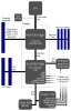
A block diagram of the adaptive clock generator is shown in Figure 2–1. The frequency synthesizer circuit generates
a programmable clock with a frequency range of 12–25 MHz. The output of the frequency synthesizer feeds the
divide-by-M circuit, which can be programmed to divide by 1 to 16. As a result, the frequency range of the MCLKO
signal is 750 kHz to 25 MHz. The duty cycle of the MCLKO signal is 50% for all programmable MCLKO frequencies.


Clock Generation
The TUSB3200 requires an external 6-MHz crystal and PLL loop filter components connected as shown in Figure 4-1
to derive all the clocks needed for both USB and CODEC operation. Using the low frequency 6-MHz crystal and
generating the required higher frequency clocks internal to the IC is a major advantage regarding EMI.

The USB interface includes an integrated transceiver that supports 12 Mb/s (full speed) data transfers. In addition
to the USB control endpoint, support is provided for up to seven in endpoints and seven out endpoints. The USB
endpoints are fully configurable by the MCU application code using a set of endpoint configuration blocks that reside
in on-chip RAM. All USB data transfer types are supported.

An on-chip phase lock loop (PLL) and adaptive clock generator (ACG) provide support for the USB synchronization
modes, which include asynchronous, synchronous and adaptive.

Universal Serial Bus (USB)
• USB Specification version 1.1 compatible
• USB Audio Class Specification 1.0 compatible
• Integrated USB transceiver
• Supports 12 Mb/s data rate (full speed)
• Supports suspend/resume and remote wake-up
• Supports control, interrupt, bulk and isochronous data transfer types
• Supports up to a total of 7 in endpoints and 7 out endpoints in addition to the control endpoint
• Data transfer type, data buffer size, single or double buffering is programmable for each Endpoint
• On-Chip adaptive clock generator (ACG) supports asynchronous, synchronous and adaptive
synchronization modes for isochronous endpoints
• To support synchronization for streaming USB audio data, the ACG can be used to generate the master
clock for the CODEC

• Configurable to support AC’97 1.X, AC’97 2.X or I2S serial interface formats
• I2S modes can support a combination of up to 4 DACs and/or 3 ADCs
• Can be configured as a general-purpose serial interface
• I2C Interface
• Master only interface
• Does not support a multimaster bus environment
• Programmable to 100 kbit/s or 400 kbit/s data transfer speeds
• Pulse Width Modulation (PWM) Output
• Programmable frequency range from 732.4 Hz to 93.75 kHz
• Programmable duty cycle
• General Characteristics
• Available in a 52-Pin TQFP Package
• On-chip phase-locked loop (PLL) with internal oscillator is used to generate internal clocks from a 6 MHz
crystal input
• 3.3-V core and 5-V compatible input/output buffers used for CODEC port interface
• Reset output available which is asserted for both system and USB reset
• External MCU mode supports application firmware development


The TUSB3200 device supports all the USB data transfer types, which are control, bulk, interrupt, and isochronous.
In accordance with the USB specification, endpoint zero is reserved for the control endpoint and is bidirectional. In
addition to the control endpoint, the TUSB3200 is capable of supporting up to 7 in endpoints and 7 out endpoints.
These additional endpoints can be configured as bulk, interrupt, or isochronous endpoints. The MCU handles all
control, bulk, and interrupt endpoint transactions. In addition the MCU can handle isochronous endpoint transactions,
such as a rate feedback endpoint to the host PC. However, for streaming isochronous data between the host PC and
the CODEC interface port, the DMA channels are provided.

Isochronous Out Transaction (host PC as source and CODEC as destination)
The steps to be followed for an isochronous out transaction are as follows:
1. MCU initializes one of the out endpoints as an out isochronous endpoint by programming the appropriate
USB endpoint configuration block. This entails programming the buffer size and the buffer base address
for both the X and Y buffers and the bytes per sample bits, setting the isochronous endpoint bit, enabling
the endpoint, and clearing the NACK bit.
2. The MCU initializes one of the four DMA channels to support the isochronous out endpoint by programming
the appropriate DMA configuration registers.
3. The host PC sends an out token packet followed by a data packet addressed to the out endpoint. The UBM
writes the data packet to the X (or Y) endpoint buffer, updates the sample count in the data count byte, and
sets the X (or Y) buffer NACK bit to a 1. Note that the number of audio samples and not the number of bytes
is written to the data count byte. Also, note that there is no endpoint interrupt generated for isochronous
endpoints. If a buffer overflow occurs, the UBM will set the overflow bit in the endpoint configuration byte.
4. The DMA channel reads the X (or Y) buffer data count byte to verify that the NACK bit is set and to obtain
the sample count in the new data packet. The DMA channel then clears the NACK bit and streams the data
to the CODEC port interface. Note that if a new data packet has not been received, the NACK bit will not
be set, and the DMA channel will not move any data to the CODEC port interface.
2.2.7.4.2 Isochronous Out Transaction (host PC as source and MCU as destination)
The steps to be followed for an isochronous out transaction are as follows:
1. MCU initializes one of the out endpoints as an out isochronous endpoint by programming the appropriate
USB endpoint configuration block. This entails programming the buffer size and the buffer base address
for both the X and Y buffers and the bytes per sample bits, setting the isochronous endpoint bit, enabling
the endpoint, and clearing the NACK bit.
2. The host PC sends an out token packet followed by a data packet addressed to the out endpoint. The UBM
writes the data packet to the X (or Y) endpoint buffer, updates the sample count in the data count byte, and
sets the X (or Y) buffer NACK bit to a 1. Note that the number of audio samples and not the number of bytes
is written to the data count byte. Also, note that there is not an endpoint interrupt generated for isochronous
endpoints. If a buffer overflow occurs, the UBM will set the overflow bit in the endpoint configuration byte.
3. After an SOF or PSOF interrupt, the MCU reads the USB frame number register and uses the least
significant bit (bit 0) value as the buffer select bit. If bit 0 is a 0 for the current USB frame, then the MCU should
access the Y buffer. If bit 0 is a 1 for the current USB frame, then the MCU should access the X buffer.
2–14
4. The MCU reads the X (or Y) buffer data count byte to verify that the NACK bit is set and to obtain the sample
count in the new data packet. Note that if a new data packet has not been received, the NACK bit will not
be set. If there is a valid data packet in the buffer, then the MCU clears the NACK bit and proceeds with
reading the data.
2.2.7.4.3 Isochronous In Transaction (CODEC as source and host PC as destination)
The steps to be followed for an isochronous in transaction are as follows:
1. MCU initializes one of the in endpoints as an in isochronous endpoint by programming the appropriate USB
endpoint configuration block. This entails programming the buffer size and the buffer base address for both
the X and Y buffers and the bytes per sample bits, setting the isochronous endpoint bit, enabling the
endpoint, and setting the NACK bit.
2. The MCU initializes one of the four DMA channels to support the isochronous in endpoint by programming
the appropriate DMA configuration registers.
3. During the current USB frame, the DMA proceeds with reading the data from the CODEC port interface and
storing the data in the X (or Y) endpoint buffer. At the end of the current USB frame, the DMA updates the
sample count in the data count byte then clears the X (or Y) buffer NACK bit to a 0. If a buffer overflow occurs,
the DMA will set the overflow bit in the endpoint configuration byte.
4. The host PC sends an iIn token packet addressed to the in endpoint. The UBM reads the X (or Y) buffer
data count byte to verify the NACK bit is cleared and to obtain the sample count of the new data packet.
The UBM reads the data packet from the X (or Y) endpoint buffer then transmits the data to the PC. At the
end of the USB transaction, the UBM sets the X (or Y) buffer NACK bit to a 1. Note that if a new data packet
has not been written to the buffer by the DMA, then the NACK bit will still be set to a 1 and the UBM will send
a null packet to the PC. Also, note that there is not an endpoint interrupt generated for isochronous
endpoints.
2.2.7.4.4 Isochronous In Transaction (MCU as source and host PC as destination)
The steps to be followed for an isochronous in transaction are as follows:
1. MCU initializes one of the in endpoints as an in isochronous endpoint by programming the appropriate USB
endpoint configuration block. This entails programming the buffer size and the buffer base address for both
the X and Y buffers and the bytes per sample bits, setting the isochronous endpoint bit, enabling the
endpoint, and setting the NACK bit.
2. The host PC sends an in token packet addressed to the in endpoint. The UBM reads the X (or Y) buffer data
count byte to verify the NACK bit is cleared and to obtain the sample count of the new data packet. The UBM
reads the data packet from the X (or Y) endpoint buffer then transmits the data to the PC. At the end of the
USB transaction, the UBM sets the X (or Y) buffer NACK bit to a 1. Note that if a new data packet has not
been written to the buffer by the MCU then the NACK bit will still be set to a 1 and the UBM will send a null
packet to the PC. Also, note that there is not an endpoint interrupt generated for isochronous endpoints.
2.2.8 Adaptive Clock Generator (ACG)
The adaptive clock generator is used to generate a programmable master clock output signal (MCLKO) that can be
used by the CODEC port interface and the CODEC device. The ACG can be used to generate the master clock for
the CODEC for USB asynchronous, synchronous, and adaptive modes of operation. However, for the USB
asynchronous mode of operation, an external clock can be used to drive the MCLKI signal of the TUSB3200. In this
scenario, the MCLKI signal would be used as the clock source for the CODEC port interface instead of the clock output
from the ACG.
 
There are chips like Cyress CYWB0124AB that hook to external memory bus, assuming you have an external memory bus.
 
We only need the one channel in our application. I looked at the ".pdf" datasheet from GFE on Thurdsday or Friday and saw nothing about a change in domain name. Apparently the USB 1.1 spec includes operation at full speed or 12 MHz., so I was mistaken about my earlier assumption. So we know this should work for a single channel at 24/96, but not for multiple channels which is where I think you are going. The idea which had not occurred to me was that a controller might have the ability to run at speeds other than the standard ones used for data transfer. In particular I'm not sure how that would work on the host controller side. In the physical layer ther are four wires, two are the power pair and two are the data pair. We know that in such a situation the data and clock are encoded on the same wires at the transmitter and decoded and separated at the receiver. Normally in this situation a receiver and a transmitter need to agree on the clock rate for this recovery to be robust and reliable. I'm not aware of how or why it might be the case that the data rate on a USB cable might vary over some range like 12-25 MHz. and have receivers track what transmitters are doing. There is an explanation here, but it is beyond my ability to discern.

I just went back to check USB 2.0 because something was nagging at me with respect to audio data and it is this. USB data uses NRZI encoding with bit stuffing. What this means is that extra bits are stuffed into the data stream to guarantee that there will be a sufficient number of transitions in the data stream by the transmitter, and they are removed by the receiver. This means that in the time domain USB data streams are non deterministic in length. Their actual length depends on the data; a zero is inserted by the transmitter and removed by the receiver for every 6 consecutive one bits. Audio data formats like S/PDIF use biphase mark encoding which does not require stuff bits. S/PDIF has a deterministic length in the time domain regardless of the contents of the data. This leads me to conclude that it would be difficult to predict how one should or could adjust the USB bit rate to "somehow" match some particular audio data format.

I go back to my earlier assertion that the USB channel must run significantly faster than the required audio data rate in order to avoid even the remote possibility of underflow, and furthermore it is in no way possible to match in any real sense a nondeterministic data stream like USB anything to a determiistic format like S/PDIF or I2S.

Have you identified any candidate controllers that may allow you to get to High-Speed operation (480 Mb/s)?

It also might be worth your while to read
§5.6.4 Isochronous Transfer Bus Access Constraints in the USB 2.0 specification since it will tell you with some precision exacly how much bandwidth you can actually have on both a full-speed and a high-speed connection. This might lead you to conclude that the was it 1394 or fire-wire might be the way to go.
 
Last edited:
Yes, I was thinking 1394 would probably be the best soulution not because of just the speed but the kind of protocol it uses, I like alot how OHCI controllers operate. If i can use only 1 channel at 24/96 does that mean that means i can only record 1 stereo channel at a time using the resolution 24/96 correct? I think I may only need 1 channel... My peripheral has 2 XLR inputs and 2 TRS/Line In inputs, 2 outputs for speakers, 2 Midi ports and 1 spdif port(s) for external clocking. The maximum amount of lines that can be recorded simultaneously are 2. And I'm cool with that, I really don't need to record anymore than that, but it is absolutely necessary that I am able to record 2 XLR or LINE IN's @ 24/96. I have ordered a few sample 1394 Integrated controllers and PHY and LLC controllers to see what one would be the best for me, I will go online and re-check witch ones I ordered and get back to you. I really appreciate your help.

Here are some of the specs off the device I am working on..

* 2 analog inputs, 2 analog outputs
* 2 channels of S/PDIF digital I/O
* 1 MIDI input and 1 MIDI output (16 channels in/16 channels out)
* 48V phantom power for condenser microphones
* Separate source selection and gain control per channel
* Headphone output with dedicated volume control


Analog Inputs — 2
* Separate source selection and gain control per channel
* Mic: XLR with 48V phantom power
* Mic preamp: >120 db EIN @ > 50 dB gain
* Line: 1/4"
* DI: 1/4"
* Maximum Input: 8.7 V RMS (balanced), or +21 dBu


* 24-bit to/from the computer
* USB type B socket (v. 1.1);
* Maximum Output: +4 dBV into 1 kohm
* Unbalanced output connectors

Headphone Output A/D
* Separate volume control—1/4" output
* > 6 mW into 50 ohm
* Sample Rate: 44.1, 48 kHz
* Dynamic Range: 106 dB (A-weighted), 103 dB (unweighted)1,2
* THD+N (line input): 0.00079% (-102 dB) @ 1 kHz1,3
* THD+N @ 40 dB gain (mic input): 0.006% (-84 dB) @ 1 kHz1
* Mic EIN (unweighted): -120 dB @ 40 dB gain, 150 ohm source
* Frequency Response: +0/-0.5 dB, 20 Hz – 20 kHz3
* Maximum Input: +21 dBu
* Input Impedance (pad off): Mic=3.5 kOhm; Line=10 kOhm; DI= >1 MOhm

Digital I/O D/A
S/PDIF I/O (24-bit)
RCA jacks
Sample Rate: 44.1, 48 kHz
* Dynamic Range: 106 dB (A-weighted), 103 dB (unweighted)1,4
* THD+N: 0.003% (-90.4 dB); -1 dBFS @ 1 kHz1,3
* Frequency Response: +/-0.5 dB, 20 Hz – 20 kHz3
 
Something you may wish to keep in mind. Modern PCs have WAY more than a single USB host controller. The machine I'm using right now has 8. So as long as you use a different port for each device you have a lot less channel/bandwidth limitation than you might think. Especially considering all the ports on my machine are USB 2.0 Not as fast as 1394 individually but there are 8 ports. And also keep in mind if I'm not mistaken 1394 is not hot swappable, the entire bus needs to be reset if a single device is removed so adding or removing a single channel from a 1394 port would require all the other streams to be interrupted and the devices to be re-initialized. Even the oldest machine I currently own right now (about 6 years old) has 2 usb host controllers.
 
Last edited:
No, 1394 is hot swappable. The only way you have 8 usb 2.0 controllers, is if you have a really hybrid cpu. Like a really, really, really expensive server motherboard.Yes, you may have 8 nodes. But each node does not have an individual controller. A single controller can support multiple nodes. If you don't believe me, Open your computer and try to find 8 usb controllers on your mothreboard (That would be 8 diffrent chips) Because I can almost guarantee you you wont. Usb 1.1 - 2.0 are alot diffrent to 1394 in the way how they communicate with eachother. Usb uses a host controller (Like on a computer) to controll and communicate to a phy controller. 1394 Is an OHCI controller, Meaning that any controller can be host depending on how much bandwith a specific controller is requesting on the bus, Or something like that..... That's whats nice about 1394 because in a 1394 network, you can use 2 of the exact same controllers for whatever. 1 for the phy and one for the host(cpu) you don't have to go shop for a host controller and then try to find a phy controller......
 
Last edited:
BlueDragon, look it up, You can not remove a device from a 1394 chain without resetting the entire bus. That's not technically hot swapping by any way I look at it.

I do not have 8 nodes. I have 8 host controllers, as reported by the Device Manager, I have 1 1394 controller, each USB controller has a seperate I/O range. There does not have to be 8 different chips, you've obviously been absent from modern electronics for a number of years cause I only have 1 CPU unit, but there are 4 cores in it, multi host controllers are just as easy to make, in fact easier because the same major system bus.
 
Last edited:
The following Information was gathered from the 1394 trade association.
**broken link removed**

What is hot swapping?
Hot swapping is the connection and disconnection of computer peripherals or other components while a system is turned on, without interrupting system operation. 1394 enables hot swapping.dd.jpg
--------------------------------------------------------------------------
The picture I attached is a Usb host controller. These are the most common controllers/transceiver that are found on most Asus and Intel motherboards, If you take a look at your motherboard, you will most likely see you have this controller or a similar controller. This controller makes Usb possible, It is the heart and soul of all usb communication. Central processing units, do not have integrated usb host controllers, (Hence the name central PROCESSING unit) The C.P.U. Processes all the Information it receives from it's sub components. If a Central processing unit had the capabilities or were Inter graded with such controllers then Texas Instruments and all the other manufactures of semiconductors would be out of business because there would be no need to make that certain semi-conductor. If C.P.U's were intergraded with such semi-conductors they would be fairly large, probably about 4-8 x there size and conduct massive amounts of heat.

I am no guru at this but I'm pretty shure I am coming correct with this...... Also you have multiple usb controllers because 1 or more controllers support full/high speed operation and 1 or more controllers support low speeds.... 1.5 mbps..... Usb Transceivers/Host controllers are a Microprocessor within themselves, So you may not have 8 separate chips, I may be wrong on that, but depending on what kind of transceiver you have, it could have multiple controllers within that chip. yes you may have a quad core, but that does not mean that each core has it's own usb transceiver integrated within itself...... I don't think. And I'm pretty sure im right on that.
 

Attachments

  • 370px-Motherboard_diagram.svg.png
    370px-Motherboard_diagram.svg.png
    39.3 KB · Views: 217
Double post, delete
 

Attachments

  • 370px-Motherboard_diagram.svg.png
    370px-Motherboard_diagram.svg.png
    39.3 KB · Views: 211
  • dd.jpg
    dd.jpg
    144.8 KB · Views: 229
Last edited:
If the host software isn't written properly to take into account that the entire bus has to reset when any device is plugged into/removed from it you'll get people that have problems juuust like this.
Firewire bus reset??? - Grass Valley Desktop Solutions Forums

Firewire is hotswappable technically but the bus requiring a reset needs to be kept in mind, it'll interupt any streams. Check the firewire standard yourself.

It's about time to clean out the inside of my PC anyways, so when I get home I'll pop open the cover and see what I have for a North and South Bridge.
 
Last edited:
yea, I know what your saying, I've heard there are issues with 1394 and hot swapping and devices malfunctioning with it.....I was just saying that it is hot swappable, but some devices can be problematic..... Good Idea to clean out your pc! Every 30 to 45 days I take my pc in the garage and take my air compressor to it, you would not believe how much dust can accumulate inside of a pc, the majority of people clean out their pc's with a simple air canister found @ radioshack... When doing routine maintenance to your pc the correct way to clean it is to 1st use an air compressor and blow off all the dust inside the pc, Including thoroughly blowing out the power supply,(It is a good Idea to wear a basic mask while using the air compressor) ( From every opening possible ) Blow out the C.P.U Fan, and if you have an graphic card, blow out the fan on that as well...After your finished with that it is recommended that you use an ELECTRICAL CLEANING SOLUTION, (SPRAY TYPE) and lightly spray your motherboard completely and then make a 2nd pass with the air compressor until dry, don't worry about shorting anything out, even if you spilt water onto the motherboard it wouldn't short out, Unless of course it was powered up, but the electrical spray is awsome to use it sucks out any moisture, while it cleans... It is also a very good Idea to remove the central processing unit(s) and clean them long with the fan(s) with rubbing alcohol to remove any pre-existing thermal compound. You should re-apply a new layer of thermal compound to the cpu and re-attach the fan. !!!Never run your Cpu not even for a second without the fan, It will result in catastrophic failure!!!! ,(Pay close attention that you do not bend or damage any pins in the removal/installation of the c.p.u) Another great Idea if you have an external video card, is to take off the fan unit, and use the same method to clean and apply thermal compound to the c.p.u(s) of the Nvidia or whatever else C.p.u that is driving your graphic card(s)..... Thermal compound looses it's cooling propertys after a period of hot/cold/hot/cold etc etc.... Thermal compound should be cleaned and added every time you clean out your pc, but in actuality you can get by doing it every 6mo.. You will notice that a P.c will run substantially better running at low temps, If you can get your temp down to 40 degrees c, that is a great temp but the lower the better... I am making an aluminum casing for my computer this winter and we are putting our computers outside, I live in Mn so the temp gets -10 alot, we will have awsome preformance....But just thought I'd share a little info!
 
Status
Not open for further replies.

Latest threads

New Articles From Microcontroller Tips

Back
Top