Continue to Site

Welcome to our site!

Electro Tech is an online community (with over 170,000 members) who enjoy talking about and building electronic circuits, projects and gadgets. To participate you need to register. Registration is free. Click here to register now.

  • Welcome to our site! Electro Tech is an online community (with over 170,000 members) who enjoy talking about and building electronic circuits, projects and gadgets. To participate you need to register. Registration is free. Click here to register now.

USB Micro-B Charger Circuit

Status
Not open for further replies.

Pemble

New Member
Hello,

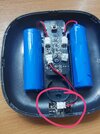
I have an electronic item which is charged via a USB micro-B charger (the trapezium shaped one).

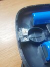
Unfortunately the charging slot on the item broke. Normally I would buy a new one but the item isn't made anymore.

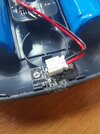
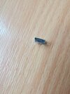
In short, is there a way I can get a new little circuit for the USB micro-B part so I can replace the broken one (with a little white "plug" to attach to the other board)? I don't even know what it would be called. Apologies for my simplistic language but I know next to nothing about electronics.

I have attached photos for reference. The circled red bit being the bit I need.

Thanks in advance.
 

Attachments

  • IMG_20210816_114544_edit_58376368629113.jpg
    IMG_20210816_114544_edit_58376368629113.jpg
    5.3 MB · Views: 264
  • IMG_20210816_114601.jpg
    IMG_20210816_114601.jpg
    4.7 MB · Views: 256
  • IMG_20210816_114553.jpg
    IMG_20210816_114553.jpg
    3.4 MB · Views: 254
Thank you. Is there a specific type / name for one that has the white "plug" attached?
 

Attachments

  • IMG_20210816_121621.jpg
    IMG_20210816_121621.jpg
    4 MB · Views: 243
I can't say I've seen one .. you'd probably have to trawl a look round maybe to find one, but .. it would be easy to cut off the plug and solder the two wires in place ?

MM
 
Search for "usb mini breakout board" or "usb micro breakout board" on ebay and you'll find all kinds of options. All of these will have a 0.1" pitch header soldered on, or holes for one. Look for the shape that will fit best.

From there, you have a couple of options. The first is as MM suggested – cut the plug of your device off and solder the wires directly to the breakout board. Red to the V+ terminal, black to ground.

The other option is to get a breakout board with a header soldered on (assuming you can't solder?) and to buy a "Dupont cable" with the same number of pins as on the breakout board (either 4 or 5). Cut off the connector of your device, and one end of the Dupont cable. Connect the red wire from your device to whichever pin on the Dupont cable connects to V+ and likewise the black wire to whichever wire of the Dupont cable lines up with ground. Note that it's extremely unlikely the colors between the device cable and the Dupont cable will match up. Match the device's red wire to whatever color matches up to V+ on the board and black to ground.

There's a third option. Get a USB A-(any type) B cable, cut off the B end and connect the remaining A cable directly to the red/black wires. Chances are good that the cable will have red and black conductors but this isn't a certain thing. Best to check with a meter to be sure.
Screenshot_20210816-052305_Edge.jpg
 
Also note – I mentioned either a mini or a micro breakout board. Your device won't care which, but micro is probably the most common. Use whichever is most convenient, with the matching cable to a USB plug pack.
 
Status
Not open for further replies.

Latest threads

Back
Top