Continue to Site

Welcome to our site!

Electro Tech is an online community (with over 170,000 members) who enjoy talking about and building electronic circuits, projects and gadgets. To participate you need to register. Registration is free. Click here to register now.

  • Welcome to our site! Electro Tech is an online community (with over 170,000 members) who enjoy talking about and building electronic circuits, projects and gadgets. To participate you need to register. Registration is free. Click here to register now.

USB charger circuit

Status
Not open for further replies.

scarygood536

New Member
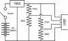
Ok so I'm building this charger. My question is doesn't the circuit need a capacitor? like a 470µF between the + and -? Also would this be a reliable project or would a circuit that doesnt use a voltage divider work better?

Schematic provided by Jameco electronics.


Thanks,
~Jeff
 

Attachments

  • USB Charger voltage divider.jpg
    USB Charger voltage divider.jpg
    51.4 KB · Views: 1,364
A 9V battery quickly drops its voltage below 7V where a 7805 regulator does not work.
You need a low-dropout 5V regulator that still works when its input from the battery is only 5.5V.

All regulators need an input and an output capacitor as shown on their datasheets. 470uF is too big and is useless to stop a regulator from oscillating.
 
The datasheets for the ICs tell you exactly what capacitors are needed.
The MC34063A is a switching circuit with many parts but it does not waste much power making heat.
The LM2937 low dropout linear regulator is simple but gets warm.
 

Attachments

  • MC34063A.PNG
    MC34063A.PNG
    15.1 KB · Views: 3,145
  • LM2937.PNG
    LM2937.PNG
    14.8 KB · Views: 784
Ahh ok... good insight. So I guess I'll recreate this circuit using the MC34063A then. That should help keep the efficiancy of the battery.
 
Maybe 80% of it =) You're dropping from 9 to 5 volts though, even a linear regulator will drop close to that much. You'll at best add a couple extra minutes from a 9v battery.
This isn't a problem with the circuit so much as it's a problem with a 9 volt battery as an energy source. They're not really designed for long term current use, they're more designed to act as low current voltage sources. If you're only using a 9 volt DC source not a 9 volt battery though you're okay.
 
Last edited:
now what if i decide to use 4 AAA rechargable batteries? or 6 volts... but the rechargables are actually 4.8 volts running at 700mAh

I have taken a look at the minty boost and it only uses 2 AAA, but the minty boost is using a inductor and the LT1302CN8-5 which is a 5volt boost convertor.
 
Last edited:
yea sure. I'm going to be charging an ipod touch. I know for a fact that it is touchy with the data lines and with the current it draws. I believe its like 2.5 volts on each data line. Thats where the voltage divider comes in. it needs to be 500mAh current.

I did make a charger for it before but the 9v battery dropped below 5 volts quickly and sometimes the ipod itself didn't want to take the charge.
 
I'm not sure what you're talking about scary, no current is transfered on the data lines, USB has separate + and - power leads.
 
iPods are all basicly the same, they can be made with fewer parts then what they show you in schematic. You need a 5V regulator, 2 NPN transistors (something like a 3904) and 2 pots. the whiper of the pot should be connected to the base of the transistors, the other 2 terminals can be connected to ground, and the output from the 5V reg. you need to adjust the pots so that the output of the transistors are 2.75V and 2V. i'm not sure of the order off of the top of my head, but i assume that (pin1=5V, pin4=ground) the order is 5V, 2.75V, 2V, ground. I know for a fact that if you strip back a USB cable then the red wire is 5V, the white wire is 2.75V, the green wire is 2V and the black wire is ground. if you don't want to use a USB cable then just try flipping pin 2 and pin 3's values, worst thing that happens is your iPod won't charge (not permenently). When i make these circuits, i allow a 5% tolerence on the output. But everyone else is right, you can't do much charging with a 9V battery, maybe 1 charge if you are lucky. but, using 6 AAA batteries will definitly give you a few more charges. bigger size batteries and more cells will increase the number of charges.
 
I'm not sure what you're talking about scary, no current is transfered on the data lines, USB has separate + and - power leads.

Sceadwian Ipods specifically the ipod touch and iphone need to see voltage present at the data lines. If the exact amount of voltage isnt present the ipod wont charge. Usually it starts to charge then the ipod suddenly stop charging (its pretty smart)
 
iPods are all basicly the same, they can be made with fewer parts then what they show you in schematic. You need a 5V regulator, 2 NPN transistors (something like a 3904) and 2 pots. the whiper of the pot should be connected to the base of the transistors, the other 2 terminals can be connected to ground, and the output from the 5V reg. you need to adjust the pots so that the output of the transistors are 2.75V and 2V. i'm not sure of the order off of the top of my head, but i assume that (pin1=5V, pin4=ground) the order is 5V, 2.75V, 2V, ground. I know for a fact that if you strip back a USB cable then the red wire is 5V, the white wire is 2.75V, the green wire is 2V and the black wire is ground. if you don't want to use a USB cable then just try flipping pin 2 and pin 3's values, worst thing that happens is your iPod won't charge (not permenently). When i make these circuits, i allow a 5% tolerence on the output. But everyone else is right, you can't do much charging with a 9V battery, maybe 1 charge if you are lucky. but, using 6 AAA batteries will definitly give you a few more charges. bigger size batteries and more cells will increase the number of charges.


ok thanks. I prolly will take the resistance of the pots and replace it with a resistor. Interesting you said 2.77 volts and 2Volts. I've heard both of them are the same from 1.5 to 2,5 volts. But, i'll trust your judgement because it sound like you have made a couple. beside only one of mine worked until the 9volt couldnt turn the 5 volt regulator on after 5 minute of charging
 
if you are looking into charging the battery while looking into powering the circuit, you can try using a MAX712 fast charging ic. it works with Ni-Cd and NiMH batteries. and thanks to some help from people on this site (audioguru) i know that you can charge the battery and power the circuit simultaneously.


MAX712

all of the information you need should be in that data sheet. it's a little confusing so i will help you out; if you want to charge a 9V battery or say 6 cells (regardless of size) leave the pins labeled PGM1 and PGM0 unconnected. i would set a charge tome of 90mins, with Voltage slope enabled; PGM3 and PGM4 are both connected to the reference voltage. For R1 the value can be determined by the equation R1=(minimum wall cube voltage-5V)/5mA. my advice would be to read the entire data sheet, there are somethings that i didn't mention that are answered by the data sheet, and some of it is just good to know.
 
Hi there,


Maybe not everything will charge without a signal of some sort on the two data lines, but many cell phones and other things will in fact charge ok without those signals. The evidence is that many commercially made portable cell phone chargers made by different companies do not have any resistors connected to the data lines and have only two power wires for plus and ground. I guess you'd have to test your actual phone or device to see if it works or not without the resistors, then add them if it doesnt.
It could be that some manu's want to make sure that the right charger is being used.

It's probably a good idea to limit current to 500ma too or at least the current the original charger put out.

Good luck with your charger(s).
 
Status
Not open for further replies.

Latest threads

New Articles From Microcontroller Tips

Back
Top