I want to controll 2 DC motors for my robot movement (i.e. Forward, reverse, left, right) the Microcontroller I'm using is PIC 16F877. I want to use PWM to controll the dirve.
**broken link removed**
the above link shows exactly what I want but with PIC 16F877 microcontroller and PWM for drive.
I havent done much work in electronics circuit and would be very glad if someone could help me modify the circuit in the above link for PIC 16F877 Microcontroller and Pwm for drive..
HELP

regards
Alia
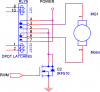
") ...If you look at the link i have given.. I dont understand that incase of the latching relays in that circuit to which pin will I give the PWM?...like will i connect the PWM to the coil? so that the switch is connected for the duty cycle..
...If you look at the link i have given.. I dont understand that incase of the latching relays in that circuit to which pin will I give the PWM?...like will i connect the PWM to the coil? so that the switch is connected for the duty cycle..