Continue to Site

Welcome to our site!

Electro Tech is an online community (with over 170,000 members) who enjoy talking about and building electronic circuits, projects and gadgets. To participate you need to register. Registration is free. Click here to register now.

  • Welcome to our site! Electro Tech is an online community (with over 170,000 members) who enjoy talking about and building electronic circuits, projects and gadgets. To participate you need to register. Registration is free. Click here to register now.

Urgent help required Pls!

Status
Not open for further replies.
Hi again,

The chips I have are QW43W (4071),QX07H (4013), QW48C (4081). These are all Maplin part numbers. I know that the flip-flop has dual inputs (basically 2 flip-flops on one chip). Could this be made to work with those ?

Also, what's involved in the microcontroller method (I'm even less familiar with these :)) ?

If it's not going to be possible to do the circuit with logic then it'd be great to see the one that turns off after one button is let go just to play around with that.


Thanks again
 
Correction, I've thought it over again and it really needs to turn off ONLY after BOTH switches are released. What do you think ?

If a microcontroller solution is much simpler I'd be willing to go down that route - I'm just eager to get this thing to work.
 
eimaj12000 said:
Hi again,

The chips I have are QW43W (4071),QX07H (4013), QW48C (4081). These are all Maplin part numbers. I know that the flip-flop has dual inputs (basically 2 flip-flops on one chip). Could this be made to work with those ?

Also, what's involved in the microcontroller method (I'm even less familiar with these :)) ?

If it's not going to be possible to do the circuit with logic then it'd be great to see the one that turns off after one button is let go just to play around with that.

Thanks again

Oh its its possible...and you're very lucky, just randomly found a 4013B in my parts box :D playing around with it now. A microcontroller would be over kill, and owuld require programming, which requires a programmer...great for loats of different projects...but if you're just begining, I don't think this type of promleb warrents the hassle involved in starting (you should at some point though!). In the meantime, here's the slightly modified circuit you asked for...motor turns off when either switch is released...

Regards,

Blueteeth.

Ps... For some reason this thing is tickling my 'problem solving gland', lol which is why I'm determinded to do it, curse my obsessive behavior :(
 

Attachments

  • Motorsw2.JPG
    Motorsw2.JPG
    40.8 KB · Views: 105
Thanks for this. The 'switch off only when both switches are released' solution is definetely the one I'm seeking now.

I'm glad this has interested you. I am very new to this but I'm really getting quite passionate about obtaining a solution for this problem. Your help is greatly appreciated once again. Like I say I will cover your time if you can solve this as I know how time consuming this can be.
 
Right, think I've done it! (I said 'think')

Instead of the OR gate (or the above modifdied one, the 'AND' gate connected to the two switches) we use the other flipflop in your 4013, an AND gate, an OR gate, and an inverter. We only need one inverter so a simple transistor would do...I'll attach the circuit for that too.

So...from the original you would require only 2 extra parts...a resistor and a transistor!! Still 3 chips, and we're only using one OR, which can be replaced with a simple transistor circuit (so we only use two chips) but first lets see if this works.

Good Luck,

A tired Blueteeth
 

Attachments

  • Motorsw3.JPG
    Motorsw3.JPG
    71.2 KB · Views: 135
HI,

Thanks for this. One question - is the 'Q pin on the top flip-flop terminated (where the X is) ? Could I just check the pins that go to ground again as on the legend it says pin 14 = then nothing ? Just being pedantic I know but just eager to get this done.

Thanks
 
eimaj12000 said:
HI,

Thanks for this. One question - is the 'Q pin on the top flip-flop terminated (where the X is) ? Could I just check the pins that go to ground again as on the legend it says pin 14 = then nothing ? Just being pedantic I know but just eager to get this done.

Thanks

Np, sorry, rushed it :D

The 'X' is simply 'no connection'. It's an output, so tying it to ground will just draw current, it serves no purpose in that part of the circuit, and because its not an input, leaving it unconnected does no harm, its simply no needed.

And Pin 14 = VCC. Sorry, you obviously knew that anyway since you built the circuit before (an earlier version) but I thought I'd include the pin numbers to make it easier to prototype, couldn't really be bothered drawing the 4013 as a 'chip', with all the pins in order...plus it doesn't show what your flip flops will be doing.

Hope it all goes well, one thing, if there are 'intemitent' problems...as in, sometimes it works unexpectedly..then include a resistor from each of the switches outputs to the pin on the 4013, so the switch has one pin to VCC, and the other with a resistor and a cap to ground, and a resistor going to the IC. Its a crap way to 'debounce' switches but its easy and cheap and it works. If you need more explaination as to the modifications, feel free to ask, but get that circuit prototyped :D

Blueteeth
 
GENIUS!

Thank for this - I've assembled it all and it works a dream! Do you have a Paypal account I could send some money to as I greatly appreciate your help with this ?


Thanks again - you're a gentleman sir.
 
Hi again,

Just a slight (I think) mod needed if you would be so kind. Sorry for this but after checking the actual

bits and pieces that will be attached to this I've just realised that the best switch pressing sequence

would be the following:

------------------------
- S1 - S2 -
------------------------

S1 pressed and held - MOTOR turns clockwise

S2 pressed and held (so now both S1 and S2 are on) - MOTOR keeps going.

S1 released - MOTOR still on

S2 released - MOTOR stops

and the opposite case,


S2 pressed and held - MOTOR turns anti-clockwise

S1 pressed and held (so now both S2 and S1 are on) - MOTOR keeps going.

S2 released - MOTOR still on

S1 released - MOTOR stops


I promise this is the FINAL version of this project. Hopefully the alterations are not too major but the above would be 100% perfect.

Also, I'm pretty sure that the last circuit was working ok yesterday, but playing around with it today I noticed that it work ok one way, but the other way when the last switch of the sequence was released (which should turn the motor off) it changed the direction of the motor ? Was this the debouncing problem you mentioned before ? I wired everything up just as in the diagram so it'd be good to know what caused this.

Thanks again
 
Hi,

Well, I sent you a pm, sorry, didn't realise you posted here as well.

Ok, looking at your description it seems an earlier version of the schematic would do the trick, the one with the 'OR' gate, albeit with some other changes..nothing major, same components, I'll post it herelater tonight hopefully.

About the debounce thing: that is probably the cause of the weird behavoir, so I've modified the debounce circuits slightly so it should give better results. The best form of 'debounce' circuits use an inverter gate, or a 'schmitt trigger'. Of course this increase the part count..but as I mentioned before if you only use one or two 'gates' from an IC (most contain 4-6 gates each) then you could use the transistor equivilent with only a few resistors and a transistor.

Just to keep you updated..

BuriedCode.
 
Hey,

Forth version :D And this time it had me completely stumped...almost to the point where I was going to suggest a microcontroller (which, if push comes to shove, I could program one and send it). But...I've finally solved the last part of the circuit and here it is.

Its a 'one shot' priority encoder. That is, the first key pressed disables the second key...so the output shows what key was pressed first. Because you wanted the motor to stay on when either switch was held, and maintain the direction (which it got form the first key pressed) the inputs are just OR'd to give a 'motor enable' again. But...a 'one shot' circuit is jsut that....it requires a reset after every key.....sure the motor would stop after both keys are released..but the direction can't be changed until its reset...so I used a cheeky little 'pulse' circuit so it automatically resets after both keys are released.

Its not alwasy a good idea to use caps and resistors with logic, but this semms pretty reliable to me. As for teh 'debounce' thing, I'm still working on a more reliable version..if you use this circuit (with the extra inverters) and you buy an inverter IC (with 6 inv's in it) that would leave 4 spare, 2 of these could be used for a great debounce circuit. So in total that is 4 IC's...because we only use one 'OR' aget, I'll draw up a transistor version, because it seems a bit silly having one whole chip just to use one gate, so this gives us 3 IC's again.

Good luck, if you want further explaination just ask,.

Blueteeth.
 

Attachments

  • Motorsw2b.JPG
    Motorsw2b.JPG
    68.4 KB · Views: 139
Hi,

Thanks for this. I' ve tried assembling this on a breadboard many times now and keep getting the same result - I press any button and the motor runs anti-clockwise and then I press the other button (motor still keeps running), and finally I release the buttons and the motor stops. Trouble is no matter which button I press first, the motor only turns in one direction ? I'd be very grateful if you could help out with this as it's like 2 am now and I've been at it for hours trying to make it work :). I should say that I used transistors with some resistors instead of an inverter like before. I've triple and quadruple checked everything I can think of so maybe a fresh pair of eyes would help.


Thanks again
 
Hi,

Well the circuit should be pretty reliable apart from one part...the 'auto reset'. And I'm cartain this is the exact problem you're having :( It seems its ridiculously sensitive to part values of the resistors/cap in that bit....did you add the diode?

As you said, its very late...so I'll look for a better way to reset it all tomorrow (day off, yays), I'll also pm about microcontrollers. Sorry if it seemed like I messed you about, and I thought that bit of the circuit would be the temperamental one..it worked eventually on my breadboard. I'm trying to keep the part count down (don't want you making order after order from maplins), and not use two many different types of gate...as that would just mean you'll have about 8 chip on a board, which seems silly for something that is essentially a straightfoward problem, just not easily solvable in logic :D.

regards,

Blueteeth.
 
Hi there,

I know that these things can take time and there are prone to teething problems so its fine. Just eager to get it out of the way now :). I had 4 1N4148s laying around so I have installed the diode also. One thing I'm wondering is how sensitive will the circuit be to the supply voltage ? I've pretty much been using a PP3 9V all along so maybe this could be a problem now ?


Thanks again for your help with this
 
Just an update, I've checked everything again and still keep getting the same behaviour. Are there any glitches in the circuit diagram maybe ? :confused:
 
eimaj12000 said:
Just an update, I've checked everything again and still keep getting the same behaviour. Are there any glitches in the circuit diagram maybe ? :confused:

Yeah, there are glitches....although I'm confident its just the reset bit, and possibly the debounce part. Again, sorry for the changes, but its a case of 50% design and 50% 'tinkering' to get the values right.

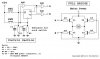
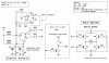
I've attached yet another schem...I think if there are any more schematics to come, it would be wise to email you, don't wanna clog up this board with jpg's :D

Unfortunately, I do not have an AND gate to hand here, and substituting a 'NAND' gate with an inverter (same effect as an AND gate) isn't a perfect mach, because two gates are more sensitive to voltage changes.......but, I've tested the reset bit with both a CMOS inverter, and a transistor inverter and it works a treat. The only problem with this now is that the debounce circuit sometimes makes the circuit reset (well, its happened once so far).

So, I'd like to get a final design up that's reliable (in your circuit) and then we can worry about substituting parts in case you want to reduce the part count or 'add' things to it. This is an experience for me, although I'm 'ok' with logic, as far as I'm aware this sort of reset isn't used anywhere else...or the logic for that matter, as most just give up and go down the microcontroller route..but as I said before, unless you already have a micro, and a programmer (as well as all the software to support it) then its not always the easiest way.

<If this works>:
This version is simplified, but appears to produce a better 'reset' pulse. As for 'debounce', yes, inverters would be great. Use this little circuit for each switch once you have an inverter:

https://www.mikrocontroller.net/attachment/423/debounce.JPG

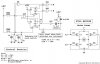
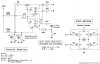
The part number '74HC14' isn't cmos...so for that you'll need either a 4069 (standard hex inverter) or a 4093 quad NAND. Now, because the second chip is a NAND and not a 'NOT' gate, you'll tie both inputs to the gate together, so it has one input and one output. You can google 'schmitt trigger' if you need to know what it does...in this application is would simply make things more reliable.

IF this works...then there are some clever tricks to reduce parts without comprimising on performance, so you'll have a smaller circuit.

Good luck,

BuriedCode.

Ps. Sorry again, I probably should have waited until I had a proper reliable circuit, tested at different power voltages before posting anything, but this seemed urgent so I waanted to keep you updated.

Edit:
Criticisms welcome by others....both FF's are meant to reset once BOTH siwtch are released (OR = 0) and although its not ideal...I can not think of a easier way to do this without bringing in many other (expensive) parts.
 

Attachments

  • Motorsw2c.JPG
    Motorsw2c.JPG
    66.7 KB · Views: 137
Last edited:
Hi,

i'll go give this a try right now and let you know how it goes. Thanks for your continued support with this as I know it's a rather tricky problem.


Will let you know asap.

Thanks
 
Hi, I've given it a try and I still keep getting the motor only turning one way i.e. I press S1 and motor turns anti-clockwise, press S2 motor keeps turning, release both and motor stops. Only thing is that the exact same thing happens when I press S2 first - the motor still turns anti-clockwise. I'm starting to think I've made some kind of mistake or maybe I've fried a component. Any ideas on what this could be ?
 
I've convinced its not reseting properly....if it doesn't reset, then on power up...once you press a button, the direction will be fixed, regardless of what button(s) you press.

As for a microcontroller....a small 8-pin PIC micro would do, I could program one, but I'm not sure about sending it....I'll have to see what envelopes I've got here.

other things to try...if you don't mind 'tinkering'...the resistor that is next to the cap in the 'reset' section...reduce its value to something like 4.7K, or increase the value of the cap.

I would also give the 'debounce' circuit a go....as any 'bouncing' of those switches would cause multiple resets....so regardless of what buttons you press..it'll reset all the time, meaning it will only go one direction. I can't say 'clock wise' or 'anti clockwise' as that depends on how you've connected the motor. As I said, theres so many things to try, which is why its taking me so long lol

I'll have to pick up a microcontorller, but I'm gonna make an order from 'rapidonline.com' soon.
Blueteeth
 
Hi,

I'll tinker about with the settings you suggested and see what happens. I'll need to order the inverter chip so that'll take a day or two to get hold of.


I'll let you know how it goes
 
Status
Not open for further replies.

Latest threads

Back
Top