In this environment, one finds four broad signal types:
1) On/Off signals. Older vehicles had a mix between 0-5v and 0-vbat (either 12 or 24 volt) levels, but most modern vehicles have standardized towards 0-5v levels.
2) Analog signals. Again, on some older vehicles you may find 0-vbat, but things are standardizing towards the 0-5v level.
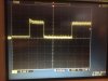
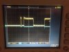
3) PWM signals. These are exclusively 0-5v levels, unless it is a power PWM which is driving lights or motors.
4) Serial bus. On these, the CANBus reigns supreme, which is a differential bus. Google it for info on its logic levels and termination requirements. I've also seen RS485 and LIN usage, but for very limited networks.