mr. mister
New Member
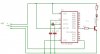
i want to feed the information output via the information line of a radio receiver into the pic (port RA0)
Also want to put in a crystal oscillator to generate 4MHz frequency.
I want to pass the output from port b to an infrared emitter diode,i know i need a transistor to amplify the current across the infrared emitting diode.
This is the circuit i have comeup with so far.
I don't know the input or output characteristics of the PIC16F84A.
Source into circuit is alsofrom the same channel from the radio receiver.
can someone tell me where i have gone wrong with my circuit? also where changes need to be made.
Thanks
forward current of IR emitter diode = 100mA