Continue to Site

Welcome to our site!

Electro Tech is an online community (with over 170,000 members) who enjoy talking about and building electronic circuits, projects and gadgets. To participate you need to register. Registration is free. Click here to register now.

  • Welcome to our site! Electro Tech is an online community (with over 170,000 members) who enjoy talking about and building electronic circuits, projects and gadgets. To participate you need to register. Registration is free. Click here to register now.

Update#2--: My Mains Heater Board's Fly-Back Regulator Has a Busted Switch (feedback power switch), but Why?

Status
Not open for further replies.
-----------------------------------------------------------------
Edit #2 ( 2022 October 16 Update)
-----------------------------------------------------------------
Tony Stewart Nigel Goodwin Bad news for me guys, it "popcorn-failed" again.

It only worked for 2 days. Yesterday night it failed. Very similar failure. This time since the surge resistor was shorted the fuse is blown (first arrow from top to bottom). The power switch was blown, again(third arrow from top); Nigel was right at his first impression.
Or maybe I made a mistake in swapping back (correct) ground and neutral?
Maybe the guy who did this saw the impedances of ground and neutral and by incorrectly wiring them, he somehow tried to prevent this kind of surges, eh? But wait a minute this does not make sense. The board looked clean it does not have history of these kind of failures.

Moreover, I think the secondary of the Flyback transformer (second arrow from top) also looks like melted and became an open circuit. (primary is measuring around 500-Ohm secondary is open circuit now). I
Correction: that one (center red arrow) is a common-mode suppression choke as rjenkinsgb pointed out.
The bottom orange wired transformer is the main Flyback transformer. It looks okay.
Resistances of orange transformer with an ohmmeter: ( I know this is not a perfect measure of inductance) 11-1.7 = 9.3 Ohms on primary 2.2-1.7=0.5 Ohms on secondary. ( Turn ratio ~ 5/93 ~ 5.4%) 220*sqrt(2)*5.7% = 16.8V so I guess this is a 12V? or 18V? regulator. That transformer has another winding (of resistance1 Ohm) on the primary side, I guess it uses this to get its feedback (probe-like action).

1665920530943.png


-----------------------------------------------------------------
Edit #1:

1665609448749.png

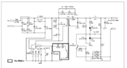
(Figure: My understanding of the flyback circuitry)
1665609493021.png

POST START: - Problem Statement -
After a long idling in spring and summer, at winter start, after a few hours of working, my mains heater stopped working.

12V Flyback regulator supplying the main board is busted. The thing did not show any sign of life.

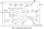
Below are some photos (that also show the close-up situation of the busted FSD210 switch - At first, I could not identify the part number of the switch, and looked at another revision of a similar Honeywell board that supplies the same line of products in my area
1665600131142.png

(Figure: Similar Honeywell board)
) https://pl-1.org/getproductfile.axd?id=8085&filename=FSD200.pdf

My question is what could have caused such a destructive heat in that area? The transistor has probably suffered a breakdown (probably because damping (muffler?) circuit did not do its job?) but why particularly now at first power-up after 7 months of idle state?

I am afraid the replacement part (FSD210) I ordered will immediately share the same fate (Or, will it?) , I want to identify the root cause of this problem.


1665599575010.jpeg

(Figure: My Honeywell board)


1665599534889.png

(Figure: My Honeywell board's power switch - unidentifiable and only the FSD210 rf017 part's number characters '17' is visible, rest is burned out, I am guessing)


and Pinout ( same orientation) The side looking the Drain pin is completely destroyed.
1665599784607.png
 
Last edited:
It's almost absolutely certain that replacing just that device will not cure it, it's a safe bet it will blow instantly if you do.

You need to replace all other faulty components - and whatever 'might' have caused the problem.

It could have been a big mains spike? - but it's suspicious that it failed after not been used for a long period - electronics usually fail when you turn them ON or when you turn them OFF, leaving them running is most reliable.

As a minimum, check the ESR of any electrolytics in the PSU - if you don't have an ESR meter, them simply replace them - also check/replace any diodes or rectifiers. Also any resistors that might have been destroyed by the high currents.

I've repaired thousands of switch-mode PSU's over many decades, they can be an absolute nightmare.

As a professional engineer I used to create 'repair kits', so if a similar unit came in again I'd simply replace all the parts in the kit for that unit - and if I ever found another dead component in one of them, I'd add that to the kit for future use.
 
The bridge rectifier looks discoloured?
(The four pin device next to the other large capacitor, just above the failed IC).

The capacitor may have failed & caused the power IC get unsmoothed DC.
 
This explosive popcorn failure can occur with rapid overheating > 100'C with moisture ingress after a long summer. It is an SMPS IC with a built-in power NFET but we don't know if it failed on power-up , but I suspect it did. It is common for inrush power to greatly exceed the steady state load power, but isn't a huge thermal problem for transient startups. But this looks like it released much more energy that a 2W transient with a 200 mW steady loss. This looks like one of those shoot-thru failures for CMOS where the interface signals exceeded the logic rails.

Using an adjustable current limiting power supply, you can safely drive the output after it is cleaned up to look for a load fault. This is one of those "really simple" SMPS IC's that is likely obsolete or going that way. I didn't check if there was a soft start on this chip.

You may also need to check the active devices with a diode tester on any nearby semi's or inject 1mA AC thru a resistor and observe the waveform.
 
Thanks very much guys. Did not expect this much thorough help. I also summarized some parts of the circuit, and tried to label them (edited the main post)

Nigel Goodwin I ordered more than one spare part for that chip in case what you said happens, I also think it is very likely.


"This looks like one of those shoot-thru failures for CMOS where the interface signals exceeded the logic rails."​

Tony Stewart That failed part is the drain of the power mosfet, basically the switch . This is beyond logic level stuff already. In a flyback converter, that voltage jumps as high as 1000V without the muffler circuit (basically it is open circuiting an inductor like in a spark-plug of a car). But this one has its muffler intact. So it will limit it to probably a few 100V.
1665610698265.png


About one unlabeled (?) strange 3 pin component (the little one next to the pop-corn failure) I could not understand what its function is.

As far as also understand this board uses transformer feedback coupling, not optocouplers. I also tried to draw the isolation line below:


1665610027806.jpeg


I will update my findings and hopefully post the results tomorrow.

It is really not like the classes when you have the only the board to work with :( I wish I had the schematic for this honeywell board.
 
The bridge rectifier looks discoloured?
(The four pin device next to the other large capacitor, just above the failed IC).

The capacitor may have failed & caused the power IC get unsmoothed DC.
After you pointed that out I triple checked them and cleaned some dirt off it. They look similar. Seems it is okay.
1665611261280.jpeg
 
It's almost absolutely certain that replacing just that device will not cure it, it's a safe bet it will blow instantly if you do.

You need to replace all other faulty components - and whatever 'might' have caused the problem.

It could have been a big mains spike? - but it's suspicious that it failed after not been used for a long period - electronics usually fail when you turn them ON or when you turn them OFF, leaving them running is most reliable.

As a minimum, check the ESR of any electrolytics in the PSU - if you don't have an ESR meter, them simply replace them - also check/replace any diodes or rectifiers. Also any resistors that might have been destroyed by the high currents.

I've repaired thousands of switch-mode PSU's over many decades, they can be an absolute nightmare.

As a professional engineer I used to create 'repair kits', so if a similar unit came in again I'd simply replace all the parts in the kit for that unit - and if I ever found another dead component in one of them, I'd add that to the kit for future use.
I have an ESR meter in the lab. In my free time I can hopefully do those things. In the lab I also have a thermal camera which also might help.

Among those suspects, one ntc thermistor parallel series resistor (ptc-burn protection) the 220vrms AC line is mildly discoloured but it is still alive (not burnt out). ( it turns out, this is also burned down to high impedance (normally it should've been short))

What if this is only a humidity+dirt ( as Tony Stewart also pointed out in his insights) combination issue? This board was not cleaned for over 10 years and this accumulated dirt looks slimy-like substance in some regions.

Edits: Corrections to component types and the events.
 
Last edited:
I have an ESR meter in the lab. In my free time I can hopefully do those things. In the lab I also have a thermal camera which also might help.

Among those suspects, one ntc thermistor parallel to the 220vrms AC line is mildly discoloured but it is still alive (not burnt out).

What if this is only a humidity+dirt ( as Tony Stewart also pointed out in his insights) combination issue? This board was not cleaned for over 10 years and this accumulated dirt looks slimy-like substance in some regions.
Seems unlikely, the board really looks pretty clean - unless you've cleaned it?, but it doesn't look like you have?.
 
It will be difficult to isolate the root cause of an avalanche effect failure where SFET RdsOn is too high (I expect) to cause the detonation like a reversed Tantalum cap. considering all the internal protection to prevent a stuck ON FET.
1665668512638.png

I doubt your schematic will be much different from the one in the datasheet. Each active device ought to be tested for bipolar current properties at least or a pseudo-ICT if you have the chops and patience.
1665668621818.png


For a high-voltage breakdown from humid dust , I might consider 10% worst case of a clean breakdown voltage like 3kV/mm for air and ? V/mm for ionic surfaces but I would expect Honeywell to meet all std. design clearances around the transformer and you have to make your own determination guess around the insulation between pins 1 and 8
 

Attachments

  • 1665667232663.png
    1665667232663.png
    54 KB · Views: 146
  • 1665668285979.png
    1665668285979.png
    46.7 KB · Views: 163
Last edited:
It will be difficult to isolate the root cause of an avalanche effect failure where SFET RdsOn is too high (I expect) to cause the detonation like a reversed Tantalum cap. considering all the internal protection to prevent a stuck ON FET. View attachment 138943
I doubt your schematic will be much different from the one in the datasheet. Each active device ought to be tested for bipolar current properties at least or a pseudo-ICT if you have the chops and patience.
View attachment 138944

For a high-voltage breakdown from humid dust , I might consider 10% worst case of a clean breakdown voltage like 3kV/mm for air and ? V/mm for ionic surfaces but I would expect Honeywell to meet all std. design clearances around the transformer and you have to make your own determination guess around the insulation between pins 1 and 8
You're vastly over thinking this? - by FAR the most likely cause is simply a failed component (odds on electrolytics or diodes) which has caused the normal catastrophic failure of a SMPSU.

A far less likely reason would be a large mains spike - messing about considering breakdown voltages etc. would be above the odds of winning the lottery jackpot.

However - nice diagram, with values and references :D

Things to check/change U1,D1-D4, fuse 10ohm, C1 (C2), C5, C7, C8, D6,D7, C3 (if duff it will almost certainly have visible damage), TX1 (rare, but happens - shorted turns, O/C, or short between windings).
 
Nigel Goodwin Tony Stewart

Okay guys. I replaced the chip. It still did not work. I powered it and traced the live voltage 220V. And I noticed it was not going through a resistor. I also bypassed(shorted) this series "safety resistor "(probably it has PTC-like behavior and it burned down to 6 MegaOhms) at the entrance of the live wire which goes into the 4-diode-bridge. After this it works. But I am not comfortable and will replace that resistor as soon as possible (not a good idea at all to bypass a layer of safety mechanism). That resistor is probably and overvoltage/overcurrent safety net apart from the fuse (I thought of it as a temperature accumulating fuse(?): It is odd that the fuse is not blown but this resistor is blown, I find this really odd)


Maybe this was all probably a rather continuous overvoltage issue (mains spike) since the safety resistor series to the live wire was also burned. Or, after I think about it again maybe not. The sequence of events is probably:

1- The power switch failed and it stayed ON.
2- The primary of the Flyback converter is turned on and stayed on for a prolonged amount of time. Which pulled lots of current from the live wire. Hence the safety resistor also burned down (but without burning the fuse - I gotta check the limits of the fuse, too).

1665681866472.jpeg

Figure: Burnt Safety Resistor ( Which I noticed after I replaced the FSD210 chip)


1665681733682.png


Figure: Tony Stewart It was really a popcorn explosion, lol. I found the cap of the package laying around the site of explosion.

Warm thanks to everyone. I am starting to like this forum, a lot.
 
Last edited:
Seems unlikely, the board really looks pretty clean - unless you've cleaned it?, but it doesn't look like you have?.
I had cleaned some dust off with dry paper towels before posting the pictures. I should've taken them earlier.


------------------------

it will be difficult to isolate the root cause of an avalanche effect failure where SFET RdsOn is too high (I expect) to cause the detonation like a reversed Tantalum cap. considering all the internal protection to prevent a stuck ON FET.
1665668512638.png


Turns out, something inside that power switch ( like a tantalum capacitor) is explosive. That component is not shown on this functional block diagram. I guess the reason why this chip failed ( if not a stuck-ON fet) still remains a mystery.
 
Nigel Goodwin Tony Stewart

Okay guys. I replaced the chip. It still did not work. I powered it and traced the live voltage 220V. And I noticed it was not going through a resistor. I also bypassed(shorted) this series "safety resistor "(probably it has PTC-like behavior and it burned down to 6 MegaOhms) at the entrance of the live wire which goes into the 4-diode-bridge. After this it works. But I am not comfortable and will replace that resistor as soon as possible (not a good idea at all to bypass a layer of safety mechanism). That resistor is probably and overvoltage/overcurrent safety net apart from the fuse (I thought of it as a temperature accumulating fuse(?): It is odd that the fuse is not blown but this resistor is blown, I find this really odd)

Not odd, perfectly normal, and working as designed - it's a special safety resistor (and should be replaced with a similar type), it not only works as a surge limiter (when you turn the power ON) it also acts as a very fast blowing fuse - fuses themselves are very slow, so the safety resistor commonly blows before the fuse (if a fuse is even fitted, often there's just a safety resistor).

Having said that - many TV's used to use 7W 10 ohm wirewound resistors as surge limiters - and even they very often blew before the fuse did in cases of PSU failure. Fuses, and particularly anti-surge ones, take an awful lot to blow them.

Maybe this was all probably a rather continuous overvoltage issue (mains spike) since the safety resistor series to the live wire was also burned. Or, after I think about it again maybe not. The sequence of events is probably:

1- The power switch failed and it stayed ON.
2- The primary of the Flyback converter is turned on and stayed on for a prolonged amount of time. Which pulled lots of current from the live wire. Hence the safety resistor also burned down (but without burning the fuse - I gotta check the limits of the fuse, too).

Assuming it doesn't blow again?, then it was almost certainly just a mains spike - not a continuous over-voltage, unless of course your supply is prone to such things? (it would be EXTREMELY rare in the UK). In the case of continuous over voltage the main electrolytic is what normally blows - I've repaired numerous satellite receivers sent back from Spain, where their mains is particularly useless. In pretty well all of those cases, simply replacing the electrolytic and surge limiter (and occasionally the fuse) cured them as the main electrolytics died because they are the component that is lowest voltage rated. It would have to get far higher than that to kill the power supply IC, which is most likely rated far higher - and everything else is on the regulated side.
 
Not odd, perfectly normal, and working as designed - it's a special safety resistor (and should be replaced with a similar type), it not only works as a surge limiter (when you turn the power ON) it also acts as a very fast blowing fuse - fuses themselves are very slow, so the safety resistor commonly blows before the fuse (if a fuse is even fitted, often there's just a safety resistor).

Having said that - many TV's used to use 7W 10 ohm wirewound resistors as surge limiters - and even they very often blew before the fuse did in cases of PSU failure. Fuses, and particularly anti-surge ones, take an awful lot to blow them.


Assuming it doesn't blow again?, then it was almost certainly just a mains spike - not a continuous over-voltage, unless of course your supply is prone to such things? (it would be EXTREMELY rare in the UK). In the case of continuous over voltage the main electrolytic is what normally blows - I've repaired numerous satellite receivers sent back from Spain, where their mains is particularly useless. In pretty well all of those cases, simply replacing the electrolytic and surge limiter (and occasionally the fuse) cured them as the main electrolytics died because they are the component that is lowest voltage rated. It would have to get far higher than that to kill the power supply IC, which is most likely rated far higher - and everything else is on the regulated side.
Yes. The mains spike is highly likely.

I also want to state a side note here. (may be an important detail and can show extra vulnerability to mains spikes)

The earth wire of the outlet on this plug was incorrectly swapped with a neutral wire for a long time ( the guy living here before me wired it incorrectly). Maybe this, in combination with the the main's spike did the thing.
Nothing else in the house was damaged. But the mains heater board (with neutral and earth swapped incorrectly) was damaged in particular. I also corrected this wiring.

(some said earth and neutral is shorted in the breaker box anyway, but still, the ground wire should never be a return path for the current -)

( I will also pickup a surge limiter resistor replacement part, thanks again for the info and insights)
 
Yes. The mains spike is highly likely.

I also want to state a side note here. (may be an important detail and can show extra vulnerability to mains spikes)

The earth wire of the outlet on this plug was incorrectly swapped with a neutral wire for a long time ( the guy living here before me wired it incorrectly). Maybe this, in combination with the the main's spike did the thing.
Nothing else in the house was damaged. But the mains heater board (with neutral and earth swapped incorrectly) was damaged in particular. I also corrected this wiring.

(some said earth and neutral is shorted in the breaker box anyway, but still, the ground wire should never be a return path for the current -)
Probably not an issue, as you say, earth and neutral are connected together anyway.
 
Fixing it is one step. Preventing future failures is harder.

Finding Root Cause and Failure Analysis with design experience to prevent future failures if necessary is much harder to do when the cause is uncertain.

Cost Reductions do often make assumptions based on how many hard power cycles are done in a lifetime vs soft switching and the number of reduced inrush surges it can tolerate. At Burroughs Unisys every new power supply design had to pass 10k power cycles which I doubt this design would pass without a CM filter and inrush protection.

A 1 A fuse is like a 1/4W resistor of 120 mOhms that has PTC characteristics like any copper to cause thermal runaway that fuse open above 150'C with the fast-blow types at 1A being less than 1 A-squared-seconds, where the fusing energy is I^2R*t.

If it failed on 1st attempt to operate the furnace after a long seasonal delay, then it's anyone's guess what the sequence could be.

My guess is an isolated moist dust breakdown voltage failure.

1). A voltage breakdown between pins 7-8 that caused a transient arc with low resistance limited by peak line voltage to the Drain of the SFET with upto a 30 A spike limited by the 10 ohm resistor and not the fuse << 1 us
2) a simultaneous fusing open of 1W input resistor and massive overcurrent of the FET when gated ON causing detonation of the epoxy case.
3) The fuse would still be cold after a 1us arc while the resistor only slightly discolored outside but open.
4) Other parts in series, would also have been stressed with transient massive over-current
 
Trivia Quiz. What can happen if you connect a PTC in series with an NTC (Inrush current limiter)? best case / worst case? (assuming appropriate values selected)
 
Trivia Quiz. What can happen if you connect a PTC in series with an NTC (Inrush current limiter)? best case / worst case? (assuming appropriate values selected)

Tony Stewart Nigel Goodwin Bad news for me guys, it popcorn failed again.

It only worked for 2 days. Yesterday night it failed. Very similar failure. This time since the surge resistor was shorted the fuse is blown (first arrow from top to bottom). The power switch was blown, again(but with a delay - third arrow from top); Nigel was right at his first impression.
Or maybe I made a mistake in swapping back (correct) ground and neutral?
Maybe the guy who did this saw the impedances of ground and neutral and by incorrectly wiring them, he somehow tried to prevent this kind of surges, eh? But wait a minute this does not make sense. The board looked clean it does not have history of these kind of failures.

Moreover, I think the secondary of the Flyback transformer (second arrow from top) also looks like melted and became an open circuit. (primary is measuring around 500-Ohm secondary is open circuit now). I
Correction: that one is a common-mode suppression choke as rjenkinsgb pointed out.
The bottom orange wired transformer is the main Flyback transformer. It looks okay.
Resistances of orange transformer with an ohmmeter: ( I know this is not a perfect measure of inductance) 11-1.7 = 9.3 Ohms on primary 2.2-1.7=0.5 Ohms on secondary. ( Turn ratio ~ 5/93 ~ 5.4%) 220*sqrt(2)*5.7% = 16.8V so I guess this is a 12V? or 18V? regulator. That transformer has another winding (of resistance1 Ohm) on the primary side, I guess it uses this to get its feedback (probe-like action).


1665909706043.jpeg
 
Last edited:
Status
Not open for further replies.

Latest threads

New Articles From Microcontroller Tips

Back
Top