Continue to Site

Welcome to our site!

Electro Tech is an online community (with over 170,000 members) who enjoy talking about and building electronic circuits, projects and gadgets. To participate you need to register. Registration is free. Click here to register now.

  • Welcome to our site! Electro Tech is an online community (with over 170,000 members) who enjoy talking about and building electronic circuits, projects and gadgets. To participate you need to register. Registration is free. Click here to register now.

Unknown infrared diod receiver broken

Status
Not open for further replies.

cmirea

New Member
I have a bicycle trainer which wasn't working and I have found out that the infrared receiver is broken.
I don't have it's schema and I don't know what I need.
I am attaching a set of pictures maybe someone can help me.
If measured when plugged in I see that the sender has 1.08V and the receiver has 3.18V. This is when I don't pedal. (I can't measure it while pedaling)
 

Attachments

  • 78bf22e7-f8ad-4ddf-92ee-57c2bed1571e.jpg
    78bf22e7-f8ad-4ddf-92ee-57c2bed1571e.jpg
    239 KB · Views: 151
  • b2d0cc5e-2916-4cd7-b55b-fb885414909f.jpg
    b2d0cc5e-2916-4cd7-b55b-fb885414909f.jpg
    142.5 KB · Views: 155
  • c5d3610f-b82d-4d2c-acda-41b7e807498c.jpg
    c5d3610f-b82d-4d2c-acda-41b7e807498c.jpg
    157.4 KB · Views: 157
  • eed49358-91e9-4b8d-8cea-58ddca3c0f53.jpg
    eed49358-91e9-4b8d-8cea-58ddca3c0f53.jpg
    246.7 KB · Views: 155
What model and manufacturer ? Image of whole receiver device?

From the pictures I'd say that is a very odd kind of damage. Seems corroded too. Have somebody thrown this device at a wall out of angry madness ?
 
If you have a small vice and a dremel you might just be able to solder a piece of tinned copper wire to it & repair it.
Cut back some of the case to expose a little bit of the lead to solder too, so long as you dont cut into the die (cup shape bit) or the bond wire it might work.
 
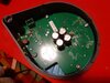
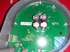
Here is what a full working one looks like....

949900C7-589C-4897-BD94-F97AF079BA0D.jpeg


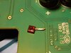
It looks like the slotted wheel that interrupts the beam got out of alignment and destroyed the IR module (emitter/detector pair) that creates a pulse every time a slot passes from the slotted wheel (the slotted wheel may also be a disk of clear plastic with "spokes" printed on it to interrupt the IR beam).

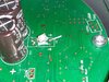
The slotted wheel fits where the dotted line is...

The IR emitter LED is where the E and phototransistor is at D.

DF052C2F-B0D3-4F7C-B26C-A7387308C349.jpeg


Your pieces are here...

DC398D01-8FCB-4B45-819F-8A1F9E3915EA.jpeg


And here...
FA3D2901-C048-4274-9FB2-1142010A3F6D.jpeg


You can order virtually any IR beam interrupt module to replace it. It will pulse when you turn the wheel and your trainer should work again.

Just try to desolder what you have...
Find a new unit with the same pin positions and spacing as the one you have.

Worst case, you can just buy individual components, aim them at each other and stabilize them with epoxy. It may take some effort to align them perfectly but a drinking straw can help stabilize everything (stick the emitter 5mm LED in one end of a short piece of straw and the detector phototransistor in the other, epoxy, let dry, cut the straw so you slotted disk fits in the gap).

You'll just have to be sure the polarity of the unit you pick matches your unit because current has to flow the correct direction.


Life is easy.
 
Last edited:
Status
Not open for further replies.

Latest threads

New Articles From Microcontroller Tips

Back
Top