R2-D2
Member
Hello All! ")
This is my first post here and I'm glad to have discovered this forum for its wealth of electronics information and help! I hope I can get some feedback for an electronics novelty project I'm working on that I intend to market soon.
I am designing an elaborate LED chaser circuit but have a few questions about it.
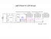
Please refer to attached schematic "LED Group Chaser.jpg" I drew up.
The circuit is a sequential light chaser for three groups of LEDs using the 555 timer and 4017 decade counter. Only three outputs are used from the 4017 counter for each group of LEDs. Individual LEDs require 3.4 volts and 24mA each. Therefore, each group of LEDs (consisting of 18 LEDs) requires 10.2 volts at 144mA. (Each branch of three LEDs requires 10.2 volts, 24mA multiplied by six branches for each LED group = 10.2 volts at 144mA.)
I am using a wall adapter as the source of 12 volts DC, 500mA.
What transistors (T1, T2 and T3) will work to handle the current required to drive the LED groups from the 4017 counter outputs?
What values do I need for the resistors (R4, R5 and R6) connected to the transistor bases?
Can I use just one resistor for each group of LEDs (R7, R8 and R9) instead of one for each of the six branches in the LED groups?
I have calculated the resistance for these resistors (R7, R8 and R9) to be 12.5Ω R = (1.8 volts dropped / 0.144 Amps) = 12.5Ω
If I need a resistor for each branch (of three LEDs), I have calculated them to be at 75Ω each. R = (1.8 volts dropped / 0.024 Amps) = 75Ω
I would also like to be able to turn ALL LEDs on (no blinking, counting, etc.) To do this, I have included a DPST switch (shown in blue) to create a connection to all bases of the transistors so that when ANY of the three outputs from the 4017 counter is active, it triggers on all three transistors. I'm not sure if this method works. Diodes (D1, D2 and D3) are connected to the 4017 outputs to prevent current flowing back into it when the switch is closed. When this switch is closed, the current from any of the three outputs from the 4017 gets split three ways to each transistor. Therefore, the current is 1/3 less to each transistor base. The transistors will still need
enough gain to power the LED groups with this decreased current after the switch is closed. Will this method work?
Another method I came up with to turn on ALL LEDs is to use a 3PST switch (shown in purple) to allow current from each of the LED groups to bypass the transistors when this switch is closed. I'm not sure if this method will work either.
Thanks for any help or suggestions!
This is my first post here and I'm glad to have discovered this forum for its wealth of electronics information and help! I hope I can get some feedback for an electronics novelty project I'm working on that I intend to market soon.
I am designing an elaborate LED chaser circuit but have a few questions about it.
Please refer to attached schematic "LED Group Chaser.jpg" I drew up.
The circuit is a sequential light chaser for three groups of LEDs using the 555 timer and 4017 decade counter. Only three outputs are used from the 4017 counter for each group of LEDs. Individual LEDs require 3.4 volts and 24mA each. Therefore, each group of LEDs (consisting of 18 LEDs) requires 10.2 volts at 144mA. (Each branch of three LEDs requires 10.2 volts, 24mA multiplied by six branches for each LED group = 10.2 volts at 144mA.)
I am using a wall adapter as the source of 12 volts DC, 500mA.
What transistors (T1, T2 and T3) will work to handle the current required to drive the LED groups from the 4017 counter outputs?
What values do I need for the resistors (R4, R5 and R6) connected to the transistor bases?
Can I use just one resistor for each group of LEDs (R7, R8 and R9) instead of one for each of the six branches in the LED groups?
I have calculated the resistance for these resistors (R7, R8 and R9) to be 12.5Ω R = (1.8 volts dropped / 0.144 Amps) = 12.5Ω
If I need a resistor for each branch (of three LEDs), I have calculated them to be at 75Ω each. R = (1.8 volts dropped / 0.024 Amps) = 75Ω
I would also like to be able to turn ALL LEDs on (no blinking, counting, etc.) To do this, I have included a DPST switch (shown in blue) to create a connection to all bases of the transistors so that when ANY of the three outputs from the 4017 counter is active, it triggers on all three transistors. I'm not sure if this method works. Diodes (D1, D2 and D3) are connected to the 4017 outputs to prevent current flowing back into it when the switch is closed. When this switch is closed, the current from any of the three outputs from the 4017 gets split three ways to each transistor. Therefore, the current is 1/3 less to each transistor base. The transistors will still need
enough gain to power the LED groups with this decreased current after the switch is closed. Will this method work?
Another method I came up with to turn on ALL LEDs is to use a 3PST switch (shown in purple) to allow current from each of the LED groups to bypass the transistors when this switch is closed. I'm not sure if this method will work either.
Thanks for any help or suggestions!
Attachments
Last edited:
 )
) 