Continue to Site

Welcome to our site!

Electro Tech is an online community (with over 170,000 members) who enjoy talking about and building electronic circuits, projects and gadgets. To participate you need to register. Registration is free. Click here to register now.

  • Welcome to our site! Electro Tech is an online community (with over 170,000 members) who enjoy talking about and building electronic circuits, projects and gadgets. To participate you need to register. Registration is free. Click here to register now.

Uni Project FM TRnasmitter

Status
Not open for further replies.

meeral20

New Member
Hello fellow friends
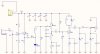
I need to make under 50mwatts FM transmitter for my uni project.All they gave us is the diagram.I have some idea about how op-amp,capacitors and resister works but when i take a look at the diagram it doesn't make any sense to me so if any1 of u please explain me where from i could begin ma project.thanks.
 

Attachments

  • diagram.jpg
    diagram.jpg
    49.5 KB · Views: 1,582
D1 is upside down, it's a varactor diode and should reverse biased in order to work.
 
Nice transmitter, better than average. Looks like a commercial design for retail. Maybe the manufacturer can provide free technical support for their ripped-off circuit?

The varicap looks the correct polarity to me. Don't forget it's an RF circuit.
 
No, it should be reverse biased, I think you're confusing it with a normal diode.

Here's an example of how a varicap should be used.

It is reverse-biased. Don't forget it's an RF circuit.

The 'should-be-done-this-way' example that was posted has too many extra parts and is 'not in the spirit' of a cheapest 'built down to a price' design :) which is one that uses the minimum of parts to do a job, with acceptable performance. These 'extra parts' do provide 'better' circuit performance (theoretcially), but on the other hand they are more circuit connections to go wrong.
 
Last edited:
I thought varactors worked in reverse bias region? How is it reversed biased?
 
Last edited:
It is reverse-biased. Don't forget it's an RF circuit.
Whether it's RF or not makes no difference to the DC voltage across the diode.

All right you tell me, in the original circuit, what's DC voltage across the diode? Please annotate the schematic.

Your example provided has too many extra parts and is 'not in the spirit' of a cheapest 'built down to a price' design. :) That is one that uses the minimum of parts to do a job, with acceptable degradation in performance.
It's a different design but it illustrates the correct way of using a varicap.
 
The varicap diode has NO DC bias. So it will work with either polarity to ground.
 
The varicap diode has NO DC bias. So it will work with either polarity to ground.
Correct, there is no bias.

A varicap won't work properly without a slight negative bias.

I discovered this myself when messing around with a varicap VCO.
 
Where does it get its negative bias from?

The cathode is connected to 0V and R6 connects the anode to 0V. If anything there's a slight positive bias from the tiny gate leakage current from Q1.

If there's something I've missed, then you tell me.
 
negative bias...

D1 is upside down,
So it is - well spotted.
[not the] correct way of using a varicap
The vari-cap diode has no bias voltage.
Correct, there is no bias.
there is no bias.
If anything there's a slight positive bias from the tiny gate leakage current from Q1.
let the preamp blast a very high signal

Why so many so 'sure' about this ? :)
I still say there is reverse bias.

Shall I go with the majority and 'say I was wrong' ? Or shall I prove it ?


Nah!!! I'll leave it open...... :D
 
Last edited:
If you let the preamp blast a very high signal then the vari-cap diode will rectify the signal and develop some bias. The audio coupling capacitor C9 might be able to hold the bias for a moment until the next audio peak.
 
Status
Not open for further replies.

Latest threads

New Articles From Microcontroller Tips

Back
Top