Electro Tech is an online community (with over 170,000 members) who enjoy talking about and building electronic circuits, projects and gadgets. To participate you need to register. Registration is free. Click here to register now.
Welcome to our site! Electro Tech is an online community (with over 170,000 members) who enjoy talking about and building electronic circuits, projects and gadgets. To participate you need to register. Registration is free. Click here to register now.
On the output of a voltage regulator I have for example 75KHz noise. If I want to put an LC filter arrangement on the output of the regulator, do I specify the 3dB point to be much lower than the 75KHz noise. If so how much lower?
On the output of a voltage regulator I have for example 75KHz noise. If I want to put an LC filter arrangement on the output of the regulator, do I specify the 3dB point to be much lower than the 75KHz noise. If so how much lower?
What sort of regulator is it?, if it's a linear one you need to build it properly as it's unstable. For that matter, if it's switch-mode it needs designing properly as well, what level is the 75KHz, and what's the output voltage?
Its a switching regulator 17.5V to 3.3V, its stable but the switching noise of the regulator is inherent on the output. Also I use linear reg's elsewhere and depending on the circuit load these can have switching noises depending on the switching frequency of the load.
So in general where is it better to design the filter 3db frequency response for an LC filter.
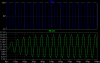
The output noise is approx. 40mV peak-peak, but I'm using it in a sensitive RF circuit.
No, I'm not talking about switching high impedance loads.
I'm talking about adding an LC filter to the output of the switching regulator to remove the 75kHz ripple.
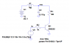
If you want to be exact a 470uH choke in series with the 10nF capacitor connected in paralell with the load might help (Fo would be 73.kKhz) but I don't think you need a tuned filter.
No, I'm not talking about switching high impedance loads.
I'm talking about adding an LC filter to the output of the switching regulator to remove the 75kHz ripple.
If you want to be exact a 470uH choke in series with the 10nF capacitor connected in paralell with the load might help (Fo would be 73.kKhz) but I don't think you need a tuned filter.
However it wouldn't be in issue for an FM transmitter, or a digital circuit so long as it doesn't switch at 151kHz or an odd harmonicfor exmple a longwave transmitter running at 151KHz or another switching PSU would cause a disaster.
Its a switching regulator 17.5V to 3.3V, its stable but the switching noise of the regulator is inherent on the output. Also I use linear reg's elsewhere and depending on the circuit load these can have switching noises depending on the switching frequency of the load.
So in general where is it better to design the filter 3db frequency response for an LC filter.
The output noise is approx. 40mV peak-peak, but I'm using it in a sensitive RF circuit.
40mV is a very low ripple level, assuming it's feeding a sensitive RF circuit then that circuit itself should have supply decoupling to remove any noise from the supplies.
Are you sure it's been picked up down the supply rails?, if the circuit is sensitive I would tend to suspect it's more likely to be picking up radiation from the switching supply - probably a lot more intrusive than 40mV on the supply?.
However it wouldn't be in issue for an FM transmitter, or a digital circuit so long as it doesn't switch at 151kHz or an odd harmonicfor exmple a longwave transmitter running at 151KHz or another switching PSU would cause a disaster.
But frequency of the load transients is relatively unimportant. Fast rising, high current edges of a low frequency switching load will excite the filter and cause it to ring. If you have a simulator, try some different examples.
That only happens at frequencies lower than or near the resonant frequency - you won't have this problem with an FM transmitter.
Anyway, I was wrong when I mentioned an inductor, you should use a ferrite bead which is a kind of inductor but it has a very low Q so it'll be damped, or you could go for a tuned filter.
I agree that you won't have a problem with an FM transmitter. I was addressing the general problems that can arise if you use an LC power supply filter without considering the load characteristics.
This site uses cookies to help personalise content, tailor your experience and to keep you logged in if you register.
By continuing to use this site, you are consenting to our use of cookies.