Continue to Site

Welcome to our site!

Electro Tech is an online community (with over 170,000 members) who enjoy talking about and building electronic circuits, projects and gadgets. To participate you need to register. Registration is free. Click here to register now.

  • Welcome to our site! Electro Tech is an online community (with over 170,000 members) who enjoy talking about and building electronic circuits, projects and gadgets. To participate you need to register. Registration is free. Click here to register now.

uln2003a and pull up method

Status
Not open for further replies.

Precious roy

New Member
Hi
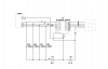
I was hoping one of you could give me some advice. I need to apply the pull up method on my uln2003 chip because my k8055 (switches in the mines) I hope I wrote that down right. So my uln2003 chip does not work.
I made a schema below. So I was wondering did I do it the right way?

Roy
 

Attachments

  • Proef1.png
    Proef1.png
    127.4 KB · Views: 5,419
Last edited:
mm i have set it up like that. but that didn’t work, because the uln2003 chip thinks the connection is open when it’s not. that why i need the pull up system on a 5-6 v battery
 
Last edited:
Is there a particular reason why you would want to duplicate the ULN2803A that is already on board the K8055? Digital outputs 1 thru 8 are already open collector outputs.

Surely all that is required is to:

Connect the Clamp pin (9) on the K8055 and the Motor common wire to +12v on the battery.
Connect outputs 1-4 to the motor as you have shown.
Connect the Gnd pin (10) on the K8055 to the -12V on the battery.

Make sure that the motor is not going to draw more than 500mA per phase otherwise you might burn the ULN2803A. If there is a risk of this, use discreet transistors with a heatsink on the outputs of the K8055 instead.

rgds
 
Pulling up any ULN type transistor array all pulled up tansistors conduct (are switched on).

Remember the ULN is fitted with NPN transistors.

Consequently you hooked up the battery (V2) inverted. :)

Pulling the bases down for absolute off would make sense to me.

Boncuk
 
Last edited:
tunedwolf
say i would want to change the k8055 later with an PIC microcontroller. then i would just need to remove the pull up (Pull down in Boncuk post) to get it to work. I’m a beginner. I’m probably doing this all wrong. hey but that better way to learn than to just do it:} (well that how it was for me when i started programming)

so Boncuk
you say pull it down how would do you do that? same as pull up instead turning it around. attach it to the - instead of the +?
 
Last edited:
so Boncuk

you say pull it down how would do you do that? same as pull up instead turning it around. attach it to the - instead of the +?

You only need pulldown resistors if the inputs float. Connected to a logic level IC the inputs always have definite state (either H or L).

Pulling down is done exactly as you described.

Don't forget to connect pin8 to ground and pin16 to the supply voltage of the stepper motor you are using. (Pin16 is internally connected to the free wheeling diodes of each transistor, which must be used driving an inductive load.)

Boncuk
 
Last edited:
Status
Not open for further replies.

Latest threads

New Articles From Microcontroller Tips

Back
Top