Continue to Site

Welcome to our site!

Electro Tech is an online community (with over 170,000 members) who enjoy talking about and building electronic circuits, projects and gadgets. To participate you need to register. Registration is free. Click here to register now.

  • Welcome to our site! Electro Tech is an online community (with over 170,000 members) who enjoy talking about and building electronic circuits, projects and gadgets. To participate you need to register. Registration is free. Click here to register now.

ULN2003 Problem

Status
Not open for further replies.

ahmelsayed

New Member
hi every one
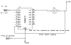
i'm trying to Drive a DC motor with ULN2003 and PIC16f877a PWM
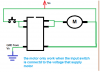
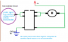
i test PWM output on a led and it works very good and when connected it to ULN2003 it didn't respond . so i test it alone when i connect the input to an external source(+5V) it also didn't respond , but when i connected it to the same voltage that supply the motor it works very well.
So can any one see where is the problem?? and help me.
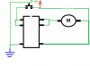
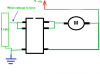
here is my connection :
 

Attachments

  • ULN2003 .png
    ULN2003 .png
    21 KB · Views: 730
Last edited:
hi,
Do you have any 'clamp' diodes on the motor other than the diode in the ULN.??

EDIT:
IF the motor works when you connect the ULN in this way,[with the input open circuit] I suspect the ULN is blown
 

Attachments

  • ULN2003 .png
    ULN2003 .png
    2.8 KB · Views: 364
Last edited:
Is the 0V or earth connection from the "microcontroller or other voltage source" joined to the 0V or earth of the ULN2003 circuit?
 
hi Eric
I depended on the diode inside ULN .
but if it is blown how could it work when the input signal (bias voltage) is only from the source that supply motor ( even it was 5 v) i.e they should share the same voltage (any value )
and the motor didn't work when the input is open circuit.
 
hi Eric
I depended on the diode inside ULN .
but if it is blown how could it work when the input signal (bias voltage) is only from the source that supply motor ( even it was 5 v) i.e they should share the same voltage (any value )
and the motor didn't work when the input is open circuit.

hi,
Are you saying it does not work when connected in this way.?

NOTE:
The Input voltage must not exceed +5V for a ULN2003, so +Vs MUST be =< +5V
 

Attachments

  • ULN2003 .png
    ULN2003 .png
    3.1 KB · Views: 548
  • AAesp01.gif
    AAesp01.gif
    54.5 KB · Views: 398
hi,
Is the 0V common of the external source connected to the 0V of the motor voltage.??

What is the voltage at the logic input pin when High and Low.???
 

Attachments

  • ULN2003 .png
    ULN2003 .png
    3.5 KB · Views: 325
hi,
Is the 0V common of the external source connected to the 0V of the motor voltage.??

The 0V's MUST be connected together

What is the voltage at the logic input pin when High and Low.???


Double post, why I dont know.!
 
Last edited:
hi,
Is the 0V common of the external source connected to the 0V of the motor voltage.??

What is the voltage at the logic input pin when High and Low.???

=============================================
I'm sorry for being late
the 0V from both arn't connected together as i read from data sheet they shouldn't connected together
=========================
the voltage at the logic input pin:
5V --------> HIGH
0V---------> LOW
 
=============================================
I'm sorry for being late
the 0V from both arn't connected together as i read from data sheet they shouldn't connected together
=========================
the voltage at the logic input pin:
5V --------> HIGH
0V---------> LOW

hi,
Where in the datasheet does it say they should not be connected together.????
 
ok i found it on a website so i just take it.(the one who wrote this information said he read it in datasheet)
============================================
now reconnect the circuit and share all the 0Vs and it works very good as it should.
so many thanks for Eric and Daves.
thanks very much.
 
Here this may help you hook the com pin 9 to the motors Vdd or the EMF diode don't work.

Did you all go back and change your post or am I going blind LOL post 8 wasn't there when drawled this and
we where still on one page .
 

Attachments

  • ul2003.PNG
    ul2003.PNG
    4.1 KB · Views: 836
Last edited:
hi Burt,
The OP's post#13, says its now working.
 
Thanks Burt
now it is working , I connect it like your circuit and it is the same as in post #8 .
so Thanks for ALL.
 
Last edited:
Eric when I posted 14 there was only post7 I don't no what happen I had to go back and read from 7 to 13 so when i got back to mine I just left it.

It usually tell if there been a post will writing drawing in my case same thing happen with the bam post

there where like 8 reply's and it didn't tell me.
 
Last edited:
Status
Not open for further replies.

Latest threads

New Articles From Microcontroller Tips

Back
Top