Continue to Site

Welcome to our site!

Electro Tech is an online community (with over 170,000 members) who enjoy talking about and building electronic circuits, projects and gadgets. To participate you need to register. Registration is free. Click here to register now.

  • Welcome to our site! Electro Tech is an online community (with over 170,000 members) who enjoy talking about and building electronic circuits, projects and gadgets. To participate you need to register. Registration is free. Click here to register now.

uc3843 Buck-boost

Status
Not open for further replies.

mrh586

New Member
Hello friends
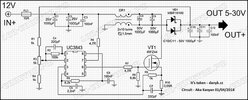
I assembled this circuit
When I measure the output with a voltmeter everything is fine.
But when something like a battery or a lamp or a DC motor is connected to the output, the output of the circuit becomes close to zero
I have been dealing with this problem for a long time and I have discussed it with different people, but I still haven't reached the result
please guide me
 

Attachments

  • Снимок3-2.jpg
    Снимок3-2.jpg
    268.9 KB · Views: 857
What are the details of your inductor? Core type and material, winding style, etc
I tested the circuit with three different inductors.
The first one is T80-26 with a value of 15 uH, the second one is T157-26 with a value of 10 uH(the same 10 turns of the coil as recommended in the map) and the third one is T157-26 with a value of 220 uH.
In all three cases, the test results were similar
- How have you built your circuit? (solderless breadboards are notoriously bad for switching power supplies)
I have soldered the circuit on the copper fiber and checked the connections several times
Thank you for your time
Please help me to get the result because it is very strange for me
There are many videos on YouTube that make and test the same circuit or similairs of this circuit
 
Do you have any more information from the original source about the circuit that you're trying to use?

Do you have an oscilloscope to monitor waveforms of the circuit?
 
I made this simulation to try to understand what was going on. When I know the properties of the inductor I'll redo things with an actual MOSFET, the proper inductances, and inductor impedance ratio.
1660261552282.png

1660261592018.png

Is about what you would expect?
 
Last edited:
I made this simulation to try to understand what was going on. When I know the properties of the inductor I'll redo things with an actual MOSFET, the proper inductances, and inductor impedance ratio.
I am really grateful
2 x 10 rounds are mentioned in the schematic
I used a core with model T 157-26 for this. (it has yellow and white color)
And the diameter of the wire is 2 mm.
In various videos that I saw on YouTube testing this circuit, smaller cores and thinner wire were used, but for use with more current, it was recommended to make the core larger and thicker the wire.
10 to 15 rounds were recommended
I measured my core with the LCR meter and it showed a value of 10 mH.
Is about what you would expect?
Yes
The simulation schematic is the same as the one I posted at the beginning of the post.
Of course, I simulated with multisim software and still did not get the result.
 
It might be the case that the actual inductance is not critical, but it seems that having both inductors be the same is critical. I'm not familiar enough with the SEPIC topology to understand why this should be the case.
 
I'm not familiar enough with the SEPIC topology to understand why this should be the case.
Papabravo, look at the transformer windings. One end sits on "ac ground" and the other is connected together by large capacitors. AC Ground can be ground or "+12V" either way there is not AC signal.

One of the windings sits on +12V or 0V with no ac at all just DC.
The other end of the windings has large AC signals.

The two large capacitors C8 & C9 from post #5 could be small and the circuit will work. With small caps, they work as a snubber. This kills ringing on the transformer.

As you know a Boost supply, the output voltage must be more than the input voltage.
This is a Boost/Buck supply where the output can be smaller or larger than the input.
At 50% duty cycle the primary winding will have one end sitting on 12V and the other end will be at 0V or 24V at 50%.
The secondary winding starts out at ground and will have an output at -12V and +12V at 50%.

The cold end of the two windings have a capacitor that shorts them together. C1,2,3.
The hot end of the windings have a capacitor that shorts them together. C8,9. See post #5.
If the two windings are not exactly 1:1 there will be massive current circling around and never leaving the power supply. If the windings are exactly 1:1 things are happy.

I have built many of these supplies and they work. I do not know why this one does not. I hope you can help. I have given up.
 
Thanks ronsimpson for the analysis. It is helpful. Looking at the schematic in post 1 it seems odd that pin 5 of the UC3843 is not connected. That pin is supposed to be GROUND. I really hate schematics that look like the actual chip that you might use as if you were doing a layout. Naturally I connected pin 5 to GROUND in my simulation and that (sorta) seems to work. I can't get it to work properly with an actual MOSFET. So far, only the voltage controlled switch seems to work. Also it doesn't seem like the wiper has much use at settings above 50%.
 
Looking at the schematic in post 1 it seems odd that pin 5 of the UC3843 is not connected
Thank you all
In other versions of the circuit, I have made sure that pin 5 is connected to the ground.
I have done the same in the assembled circuit
If this is not done, the MOSFET will be destroyed quickly
 
...
Try adding a cap to the VCC pin.
I added a 10uF capacitor from Vcc to GND. At about 13 msec of simulation time things just stopped moving forward. I was able to halt the simulation, so it was still trying to do something but not making any progress.
 
Do you have any more information from the original source about the circuit that you're trying to use?

Do you have an oscilloscope to monitor waveforms of the circuit?
Sorry
I just saw your post
I tested with two different power supplies and both were switching type
One is 12 volts 3.3 amps and the other is 15 amps
Unfortunately, I don't have an oscilloscope
 
Made the change and it gets a bit further but still freezes with the duty cycle going approaching 0
1660415641636.png

1660415684920.png

The model for the UC3843a is a hierarchical schematic and maybe it would be helpful to examine it in more detail.
 
Hi

I think there is an error in the FB circuit shown on the TS's schematic.
The internal feedback reference voltage is 2.5v and is generated internally, so the REF pin should not be connected to the feedback circuit, it is intended for the oscillator components. So that wire should be removed. Additionally, Configure R3 as a variable resistor and change it to 10K, then connect the feedback pin to the junction of R3/R4, the output voltage will then be adjustable between 5v-30v.

The previously mentioned zener should be added as well.

See below:

1660438716006.png


1660438751052.png
 
Last edited:
Status
Not open for further replies.

Latest threads

New Articles From Microcontroller Tips

Back
Top