Continue to Site

Welcome to our site!

Electro Tech is an online community (with over 170,000 members) who enjoy talking about and building electronic circuits, projects and gadgets. To participate you need to register. Registration is free. Click here to register now.

  • Welcome to our site! Electro Tech is an online community (with over 170,000 members) who enjoy talking about and building electronic circuits, projects and gadgets. To participate you need to register. Registration is free. Click here to register now.

uA78HGA

Status
Not open for further replies.
Dear Forum Members,
There are a number of uA78HGA in my possession, so let's build a power supply, normally these regulators are adjustable from 5 volts.
Now I was wondering is there not a trick to make these regulators work from a lower voltage, it was also done with the uA723 ic in the past which originally could also work from 7 volts.
Is there anyone who has an idea to let the voltage of the uA78HGA lower than the minimum 5 volts that can now come out.
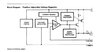
Below some details of the uA78HGA.
Greeting,
Pim

ScreenShot094.jpg


ScreenShot088.jpg


ScreenShot089.jpg

ScreenShot090.jpg

ScreenShot091.jpg

ScreenShot092.jpg

ScreenShot093.jpg
 

Attachments

  • ScreenShot087.jpg
    ScreenShot087.jpg
    20.2 KB · Views: 161
  • ScreenShot089.jpg
    ScreenShot089.jpg
    20.7 KB · Views: 168
The only way I can think of getting a lower output voltage than 5 volts is to scale the output voltage up using an op amp. As the reference voltage to the error amplifier is fixed at 5 volts the IC attempts to keep the control input to the error amplifier at the same voltage. (5 volts.) So for example if you wanted 2.5 volts out then the resistors in the op amp circuit would have to double the voltage. You may have stability problems using this idea.

Les.
 
Thanks for your comment, don't see how that should be done yet, but if it causes stability issues, that's a new problem.
Had the idea to use an LM317 up to 5 volts and then switchable, but that causes a lot of hassle with wiring.
Greeting,
Pim
 
Another possible solution might be to connect the common pin to a STABLE negative supply. That should subtract from 5 volts. So if you wanted 3 volts output the negative supply would need to be 2 volts.

Les.
 
Since the output voltage of the uA78HGA is relative to it's ground pin, another way to lower the voltage would be to shift it's gnd pin negative.

If the GND pin is at -2 Volts, then the output would be 3 Volts. Whatever you use to drive the GND pin needs to handle the ~10mA operating current of the uA78HGA .
 
Hoi Les,
That's a good idea, I'm going to try that out tomorrow.
This does mean that the uA78HGA will have a floating ground connection.
Pim
ScreenShot095.jpg
 
Hoi Chris,
My point is that it is possible to regulate from a low voltage, so as not to immediately put 5 volts on a circuit.
So that negative voltage could also be switched if the circuit where the power supply is connected can handle the 5 volts, then switch and adjust from 5 volts.
 
Could you take a photo of the device’s top? I would like to read the date code.

If these are legitimate NOS devices, they will be worth good money.
 
Hoi Les,
That's a good idea, I'm going to try that out tomorrow.
This does mean that the uA78HGA will have a floating ground connection.
Pim
Do not let the ground pin float. It must be tied to some stable point.

The uA78HGA regulates it's output to be 5 Volts above the ground pin. If it were left floating, then the output could be as high as the input, or probably be a volt or two below the input voltage.
 
Do not let the ground pin float. It must be tied to some stable point.

The uA78HGA regulates it's output to be 5 Volts above the ground pin. If it were left floating, then the output could be as high as the input, or probably be a volt or two below the input voltage.
That is clear, the ground connection will be at a low negative voltage.
Preferably adjustable.
 
Do not let the ground pin float. It must be tied to some stable point.

The uA78HGA regulates it's output to be 5 Volts above the ground pin.

Not quite - it's output is set by the control pin, which has a 5V reference offset from the ground pin.

The "ground" could be fixed at -5V and the control would then be zero - referenced.
 
Could you take a photo of the device’s top? I would like to read the date code.

If these are legitimate NOS devices, they will be worth good money.
This is like Antiques Roadshow where some guy turns up with some rusty metal and it turns out to be worth 1M dollars. Looking forward to the answer.

Mike.
 
It works with the LM317 and that can also be proven in Tina software, but unfortunately there is no model of the uA78HGA available in Tina software.
ScreenShot099.jpg
 
Hmmmmm,
Difficult to say accurately, but the “N” of the National Semi logo doesn’t look quite right. **broken link removed****broken link removed**
 
Hmmmmm,
Difficult to say accurately, but the “N” of the National Semi logo doesn’t look quite right.
image.jpg
 
Last edited:
Not quite - it's output is set by the control pin, which has a 5V reference offset from the ground pin.

The "ground" could be fixed at -5V and the control would then be zero - referenced.
But if the "ground" pin were left floating, then there is no return path for the internal operating current, and no point for the internal 5V reference to know where it's zero point is.

Now, I have no personal knowledge of this condition, but a couple years ago Flyback put up a post where he complained that the output of a regulator that he was using went close to the input when it lost it's ground connection.
 
Status
Not open for further replies.

Latest threads

New Articles From Microcontroller Tips

Back
Top