Continue to Site

Welcome to our site!

Electro Tech is an online community (with over 170,000 members) who enjoy talking about and building electronic circuits, projects and gadgets. To participate you need to register. Registration is free. Click here to register now.

  • Welcome to our site! Electro Tech is an online community (with over 170,000 members) who enjoy talking about and building electronic circuits, projects and gadgets. To participate you need to register. Registration is free. Click here to register now.

Two Stage Amplifer

Status
Not open for further replies.

andrebc

New Member
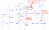
The attached Circuit is supposed to give an amplified signal to a speaker of 50 Ohms, the common emitter gain AV is about 95, Rout is around 1.7K and the input impedance of the Follower is about 5K and its output is 50 Ohms, the issue is mis-match impedance I am having between the 1.7K CE output impedance and 5K input impedance of the buffer. It’s like a puzzle I could not make my buffer input resistance at least 10 times higher than my CE output impedance without affecting the output impedance of the follower which is supposed to be around 50 ohms to drive the speaker. I also tried using a voltage divider technique instead of self-biasing to overcome this mismatch impedance issue but I could not get it to work. I used R1=60K and R2= 47K, and RE=300 ohms for the buffer, instead of R(B)=215K. I basically get nothing out to the speaker. Any body can think of how this can be resolved. I know there are other ways of designing an amplifier among which is the use of MOSFETS or Darlington configuration.
 

Attachments

  • Amplifier.doc
    43 KB · Views: 251
First, Q6 has no base bias due to C15 blocking all DC current, so it's cutoff. You need to connect the 215K resistor at the junction of C15 and the base of Q6. Also 215K is too large to bias the output transistor at a reasonable current to drive a 25Ω load (the 50Ω emitter resistor in parallel with the 50Ω speaker.

Second, the 1nF output coupling capacitor cuts off all frequencies below 3.2MHz, so you are obviously not going to hear anything, even if the amp worked. It should be more like at least 100µF.

Third, even under the best of circumstances an emitter follower makes a lousy speaker amp. You should use an audio amp IC for that purpose.
 
First, isn't the 10uF connected to the base of the 2nd 3904 in the wrong place.? As the circuit is drawn, that transistor has no bias.
 
Are we taking impedance matching maybe too seriously? Ain't impedance matching only critical for things like power transmission systems and RF amplifiers, where transformers and RF transistors are expensive?

If it's something like an an audio amp, then just adding another BJT into the cct. solves the problem.
An opamp circuit is an example of great performance where there is a enormous amount of impedance mismatch, opamp inputs are GigΩ+, while the resistors around them only kΩ. Plus, an audio amp speaker output Ω is only milliohms, which is much smaller than 8 Ω (or whatever ohmage the speaker is).
 
Last edited:
Are we taking impedance matching maybe too seriously? Ain't impedance matching only critical for things like power transmission systems and RF amplifiers, where transformers and RF transistors are expensive? If it's something like an an audio amp just adding another BJT into the cct. solves the problem. An opamp circuit is an example of great performance where there is a enormous amount of impedance mismatch, opamp inputs are GigΩ+, and the resistors around them kΩ. Plus an audio amp speaker output Ω is milliohms, much smaller than 8 Ω (or whatever ohmage the speaker is).

Yes, impedance matching is mostly a bad thing - and of no relevence here.

The circuit won't work because the capacitor is connected wrongly, and he's also assuming (incorrectly) that making the emitter resistor 50 ohms makes the output 50 ohms.

The entire thing seems bizaarre?, and he seems to be wanting to feed a speaker with it? - perhaps the OP should tell us EXACTLY what he's wanting to do?.
 
Nobody makes a 50 ohm speaker. The amplifier should be designed for a normal 8 ohm speaker. Then it will be more obvious that a single transistor emitter-follower can't drive it without wasting a huge amount of power.
 
please i need A circuit diagram for 8ohms speaker..i want to connect 5speakers and one hoofer to it
 
Each speaker usually has its own amplifier. If you connect five 8 ohm speakers in parallel then the resulting 1.6 ohms is like a dead short to most amplifiers.

I don't know what is a 'hoofer". A sub-woofer usually has a lowpass filter and its own amplifier.
 
I looked at the original circuit, omit the 215K and capacitor and it's not that bad, it'd 'work' of sorts, but it would be very quiet and rather tinny sounding. Wouldn't be very good for driving five 8Ω speakers though!

What about five audio ICs instead?
 
Last edited:
Yes, impedance matching is mostly a bad thing - and of no relevence here.

The circuit won't work because the capacitor is connected wrongly, and he's also assuming (incorrectly) that making the emitter resistor 50 ohms makes the output 50 ohms.

The entire thing seems bizaarre?, and he seems to be wanting to feed a speaker with it? - perhaps the OP should tell us EXACTLY what he's wanting to do?.

Guys thank you all for your contributions, the capacitor C15 does not belong to where it is, I just made that mistake when I re-drew the circuit, C15 is just a coupling capacitor betwen the two stages. Both my CE and EF are biased properly you could check that with any simulation software

Yes mismatch impedance here is an issue, calculate Rin of the follower you will see it is around 5K while the output impedance of CE is 1.7K this means I am losing most of the signal between the two stages. RIn of the follower should be at least 10 times higher than Rout of CE for a signal to be buffered.

I know this is not an efficient way of designing an amplifier, if it was up to me i would use a mosfet for my buffer as it has input impedance that is equal to infinity and all I would have to worry about is selecting the right value for Rs( sourse resistor) to match the impedance of my load also I could have used some darlington configuration. But this was a lab task with all this restrictions.
 
Yes, impedance matching is mostly a bad thing - and of no relevence here.

The circuit won't work because the capacitor is connected wrongly, and he's also assuming (incorrectly) that making the emitter resistor 50 ohms makes the output 50 ohms.

The entire thing seems bizaarre?, and he seems to be wanting to feed a speaker with it? - perhaps the OP should tell us EXACTLY what he's wanting to do?.

By the way RE=50 in the buffer is not necessarily supposed to be there, I just tried that so I can get an Rout for my follower equal to 50 ohms, but some other configuation could also results in Rout= 50, the thing is how to satisfy all these 3 conditions:
1-Rout of CE << ( much less than ) Rin of Follower
2-Maximum higher gain for the CE with a 10mW budget power, VCC =5V
3-Rout of the follower=50 ohms
 
Guys thank you all for your contributions, the capacitor C15 does not belong to where it is, I just made that mistake when I re-drew the circuit, C15 is just a coupling capacitor betwen the two stages. Both my CE and EF are biased properly you could check that with any simulation software

Yes mismatch impedance here is an issue, calculate Rin of the follower you will see it is around 5K while the output impedance of CE is 1.7K this means I am losing most of the signal between the two stages. RIn of the follower should be at least 10 times higher than Rout of CE for a signal to be buffered.

No it's not an issue, while it would be better higher, it's losing FAR less than impedance matching would. Impedance matching is at theoretical best only 50% efficient, and a completely wrong choice for the vast majority of applications.

I know this is not an efficient way of designing an amplifier, if it was up to me i would use a mosfet for my buffer as it has input impedance that is equal to infinity and all I would have to worry about is selecting the right value for Rs( sourse resistor) to match the impedance of my load also I could have used some darlington configuration. But this was a lab task with all this restrictions.

Like I said earlier, the value of the emitter resistors doesn't equal the output impedance - but as you've never actually given us the requirements of the assignment it's hard to know what you're supposed to be doing?.
 
This impedance matching issue usually comes up when there's not enough silicon (or tubes) in a circuit. Maybe that is the whole point if this part of an academic assignment.

In the commercial world, IM is only critical for things like power transmission systems and RF amplifiers, where transformers / RF transistors are expensive, and costs need to be kept down, such as an amplifier for CB Radio (burner), the performance is highly dependent on IM, since it only has a single RF transistor. OTOH, an audio amplifier IC itself has dozens of junctions and is impedance full of mis-matches all over the place! Then the outside the IC, output ohmage of an amp driving an 8ohm speeker is milliohms.

I can see a problem on the circuit (if still there), delete the 215K and 10 uf. & connect Q6 base straght to Q1 coll.

It's desireble to have an impedance mismatch going on between the two stages. A emit-follower's input is often a lot higher than the sourceZ it's connected to. Just like the output ohmage of a good amplifier is much lower than the '8 ohm' speaker.

Finally, if Q6 really is going to be a class-A output stage driving speaker load worth just 1.6 Ohms, then you'd need to add another transistor to boost the current. Make it a darlington or alpha pair or whatever it's called. Then you'll need to reduce the value of R16, you could make it a light bulb and the class-A amplifier project can double as as light and heat too. :)

Unless the text of the original assignment is posted here in it's original context, it's likely newsgroup posters misunderstand and all go off on different tangets! :)
 
Last edited:
in any case thank you guys a lot for your feedback I am really learing a lot from this forum, But I still believe the reason my circuit did not amplify my signal because of the impedance mismatch. when I troublehoot my circuit i get an amplified circuit right after the CE , I tested the follower I made , it also gives a 0.85 gain almost unity gain but when I put every thing together, just nothing comes out. Vin was 10mV this is like an RF signal and as I learned in the class and as the assigment asks and it is recommended in Razavi Behraz book, Fundamentals of Microelectronics, that the Rin of EF has to be at least 10 times higher than that of the CE for amplification to happen. You could ckeck this out in the text I just mentioned.
 

Attachments

  • Amplifier.doc
    106.5 KB · Views: 196
in any case thank you guys a lot for your feedback I am really learing a lot from this forum, But I still believe the reason my circuit did not amplify my signal because of the impedance mismatch.

You believe wrongly.

when I troublehoot my circuit i get an amplified circuit right after the CE , I tested the follower I made , it also gives a 0.85 gain almost unity gain but when I put every thing together, just nothing comes out.

If you're getting nothing out, then you're doing something badly wrong.

Vin was 10mV this is like an RF signal and as I learned in the class and as the assigment asks and it is recommended in Razavi Behraz book, Fundamentals of Microelectronics, that the Rin of EF has to be at least 10 times higher than that of the CE for amplification to happen. You could ckeck this out in the text I just mentioned.

Never heard of it, and you've either misquoted it, or it's completely wrong.
 
I still believe the reason
You believe wrongly.

These belief standoffs are resolvable after the intake and digestion of good information. We're lucky here because we have some objective reality to use as a source of information. (not so lucky are people who are very religious being not willing to 'put god to the test')

when I put every thing together, just nothing comes out.

What's the load impedance? For some reason I'd gotten the idea it's 8 Ω

What's the frequency? For some reason I have the idea it's 'audio'

Ideally, andrebc will set up the test circuit again, and record scope traces at various points in the circuit and then post them, appropriately identified. Unless something like this happens, it's just going to stay a belief standoff !
 
Last edited:
It's nothing to do with 'belief' - simple ohms law complete disproves it.

Impedance matching passes only 50% of the signal, feeding a low impedance into a higher one passes MORE than 50%, depending on the ratio. Feeding a source impedance into a load impedance of at least five times the source impedance is usually considered sufficiently high.
 
The value of the output capacitor (1nF) is so small that it passes only radio frequencies to the 50 ohm load.
If its value is increased to 100uF and the value of the emitter bypass capacitor (10uF) also increased to 100uF then amplifier will have some gain.

The value of the base bias resistor (215k) for the output transistor is so high that the transistor is almost cutoff when it tries to have a current of 52mA into the 50 ohm emitter resistor. It should be about 6.8k ohms.
 

Attachments

  • two stage amplifier.PNG
    two stage amplifier.PNG
    46.9 KB · Views: 172
It's nothing to do with 'belief' - simple ohms law complete disproves it.

When someone believes something, whether it's an irrational belief or not, it is an issue to them. Beliefs motivate us most of all, second only to being chased by a predator. So if it's just a case of Ohm's Law, what's been going wrong here then with the difference of belief? Otherwise it's a standoff of righteousness verses ignorance (with a possiblity of role reversal).

(1nF) is so small that it passes only radio frequencies to the 50 ohm load.
Maybe it's an RF circuit?


The value of the base bias resistor (215k) for the output transistor is so high that the transistor is almost cutoff when it tries to have a current of 52mA into the 50 ohm emitter resistor. It should be about 6.8k ohms.
Sorry to say this, but the author of the circuit said a few postings ago that the circuit you're looking at was drawn wrong. The OP should really post the circuit, along with more information, or we'll just all keep guessing!
 
Last edited:
The circuit was drawn wrong with the base bias resistor (215k ohms) not connected to the base of the output transistor.
I moved the coupling capacitor so that the 215k resistor provided a tiny amount of base bias current but the resistor value was much too high.
 
Status
Not open for further replies.

Latest threads

New Articles From Microcontroller Tips

Back
Top