Continue to Site

Welcome to our site!

Electro Tech is an online community (with over 170,000 members) who enjoy talking about and building electronic circuits, projects and gadgets. To participate you need to register. Registration is free. Click here to register now.

  • Welcome to our site! Electro Tech is an online community (with over 170,000 members) who enjoy talking about and building electronic circuits, projects and gadgets. To participate you need to register. Registration is free. Click here to register now.

two row long tail headers for breadboards

Status
Not open for further replies.
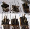
Not that I am being lazy, just a little frustrated. I've paged thru my mouser/digikey/etc catalogs looking for some 2 row headers that have a long enough tail to split and bend to fit the midline of a breadboard row. I know they're out there, I've seen them used in project photos often but no part numbers or references are given. Would someone kindly toss some appropriate part# references or URLs please? :)
 
I a'm not sure what you want, here are two questions the will help me understand what you want.
Are you looking for male or female?
Is the spacing between the pins to be 0.3"?
 
Maybe I'm missing the point here..but I just use these:

**broken link removed**

Then bend the 'long leg' at a right angle to the plastic holder, and straighten out the ither side..

Failing that, knocking up a simple adapter on stripboard works.

Blueteeth
 
standard male header pins, 2.54mm or .1in the problem with inverting typical pins such as above is that often the tail side is too short for a socket to maintain connection without popping off. i have found some that are made by various mfrs with a mating length of .5in and a tail length of .8in which would work perfectly -- but of my growing list of supply sites, nobody carries them.
 
You initial post about the middle of the breadboard row was confusing.

But if what you need is a pin header that will stay put in the breadboard you can solder the short ends of 2 together and have long pins on both ends. I use a post it note with the glue sides up to hold the little bits in place while I make the first joint. A bit of liquid flux helps.
 
Last edited:
aye, i mean for one row to span the inner column of the left hand side and the other row to span the inner column of the right hand side. i might have to do that in the short term but i'm still looking for long tail headers for the future connectors =]
 
Gotcha. I would make a PCB. :)

If you only need a few pins there is a connector in the layout of a DIP but instead of a chip the pins come through to the top where you can solder to them. On the top side the pins look like V's so you can place a wire or component lead into the slot and solder.

I can not think of what they are called. I have some in 14 and 16 pin packages. Maybe the come in larger sizes.
 
Hi,

I know this is really geeky but when I prototype with breadboards I always need double row headers for IDC cables (AVR pinout, PIC dev boards. LCD's etc..) I tried looking for the long pin headers, but gave up. So, 3 minutes with standard single row headers and stripboard...I built these.

You only need to cut between the rows of pins, I did it with a craft knife. The cool thing about this is you can make a 2x20 double row header, then cut it up into smaller ways, that way you only really need to make a couple of these.

Blueteeth.
 

Attachments

  • headers.jpg
    headers.jpg
    61.1 KB · Views: 662
Hmmm,
I'd make a PCB too :D

but is what you are after wire wrap connectors? The wire wrap parts have very long leads on them...
 

Attachments

  • 1367.pdf
    355.5 KB · Views: 685
Last edited:
Thanks Erick. I was thinking of the DIP Component Headers

But in general building a board is a better option for the OP.

I would agree a small pcb is a better job, I use that method for 14/16 pin IDC's for LCD displays.

The DIP through pin component headers [on pdf] are useful for terminating loose wires from cable ends.

For reference you can/could get the first version, [DIP] with a plastic box cover that clips onto to the header base.
Ideal for making up your own modules, osc and the like.
 
Last edited:
If you were addressing me then no. These look like a DIP chip but have a cover you take off that exposes posts you can solder to. The posts have a notch in them to take a wire.

No, sorry, I wasn't addressing you; I was just stating I would make a pcb, as well (as you.) However, I was directing the question to the OP, who seems to want
2 row headers that have a long enough tail to split and bend to fit the midline of a breadboard row

My thoughts were he was after an IDC header which would span the gap on a breadboard, so I thought of an IDC header for wire wrap which he could bend the tails at 90 degrees twice to cross that span.

The connectors you and Eric are talking about would work well, and look very cool. They wouldn't require the bending to fit....
 
thank ya guys. you know, you can never find all the pages in your history that you "just visited" over the last ~72 hours where you saw various things. i know somewhere on ladyada's (adafruit) site i saw pix of these long tail headers. nor can i find the reference in the forums that led me to it. nor on avrfreaks :-X oh well. when i find them again, i'll try to find this topic and bump it with a url or two.

in the mean time i think i'll go with the small board idea that most people seem to be using. SparkFun has a simple one for a buck at https://www.sparkfun.com/commerce/product_info.php?products_id=8508 and i've been re-learning a few things in eagle making my own design. i figure if i'm going to do a board, i might as well try to learn something additional in the process.

on a side tangent that should probably go into the MCU sub, is it more appropriate to tie Vcc of the programmer and the breadboard and float ground, or tie GND and float Vcc? i ask because a variety of programmers that i've seen have rather a mix of approaches. personally i've had better luck tying both Vcc and GND between the breadboard and programmer rather than letting one float. i'm using the usbtinyisp and attiny13a chips.

</end of rambling>
 
Last edited:
Fyi, I found a website (www.samtec.com) that lets you build a part number bit by bit and then order samples of it. Thusly you can build the headers that I'm looking for. TSW-150-28-G-D-001 should do nicely. .230in mating length with .8in tail length.

bookmark it ;-)
 
Status
Not open for further replies.

Latest threads

New Articles From Microcontroller Tips

Back
Top