Continue to Site

Welcome to our site!

Electro Tech is an online community (with over 170,000 members) who enjoy talking about and building electronic circuits, projects and gadgets. To participate you need to register. Registration is free. Click here to register now.

  • Welcome to our site! Electro Tech is an online community (with over 170,000 members) who enjoy talking about and building electronic circuits, projects and gadgets. To participate you need to register. Registration is free. Click here to register now.

Two PIR motion sensors follow-up

Status
Not open for further replies.

TinkerD

New Member
The thread started back in 2013 (https://www.electro-tech-online.com/threads/neeed-some-help-with-dual-pir-sensor-circuit.138698/) is extremely close to what I need but as the parts I'm using are a bit different and the thread had a shift a few years later, I thought a new topic might be better than reactivating that one.

But indeed, this is also a setup to drive LED lights with two PIRs, in this case along a driveway with a PIR at each end so arriving and departing vehicles can trigger the lights.

The DC>DC solid state relay I'm using has a wide control voltage (3-32DC @ 3-25mA) and the 12v DC PIRs I am getting are designed to drive items such as LED lights up to 100w @ 12vDC but I do not have any real specs for them beyond that. The load side of the PIRs will only be driving the relay.

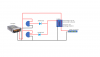
The original diagram discussed in that old thread was using a transistor to adjust voltage for the relay and honestly, confused me a bit so the attached diagram is what I think I should be doing.
 

Attachments

  • Lights.png
    Lights.png
    74.8 KB · Views: 219
Welcome to ETO, TD!

Not sure if your asking for advice, but...

If you are, the design you posted should work just fine.

I am curious, though, what PIRs you're using.
 
Hi Bob. thanks and yes :)

I guess I should have said more clearly that I'm looking for comments, advice, etc to confirm if I'm headed down the right path. While I have done lots of stuff, both low and high voltage, this is the first time I will actually use discrete components like a diode. It took some time to marginally get my head wrapped around the specs and I'm still really unclear about Schottky and all the different diode use cases but one-way electric traffic is a cool idea.

Anyway, I actually ordered two different PIRs, both from ebay:
180 degree: **broken link removed**
This 180 comes in 2 flavors, 12vDC or AC

140 degree: **broken link removed**

They are similar in that both are weather resistant and have a time out that extends to about 10 min which is desired.

One thing that I noticed after posting is the 140 degree unit mentions "Load power: 5W~100W".
The relay is way under 5 watts of load so I'm wondering if I will need to add some load to the output of one or both PIRs to actually get them to trigger. This could be OK as I could add a bit of LED strip before each diode and locate them in the hallway or some similar place as indicators of activity at the top or bottom of the driveway. A bit problematic getting the wire to a good location but it could be a nice added feature.
As a side note, I'm also putting in a photo sensor on the AC side to disable everything during daylight hours.

BTW, what is "TD!"
 
I'd use 1n4001 diodes, but it looks as though it'd be Ok.
If the Pir's have contacts within them you wont even need diodes, wire or would work.
Is there a particular reason why you went 12v, Selv or something.
 
BTW, what is "TD!"
Just my being lazy - TinkerD.

The relay is way under 5 watts of load so I'm wondering if I will need to add some load to the output of one or both PIRs to actually get them to trigger.
Unlikely. Both PIR circuits trigger by a change in the Infrared detector's window map, not any load on the output circuit.

Also, I am not at all clear how the output of the two different detectors is defined (12VDC from a relay or from the detector circuit or what).

So, it might be best, once you get them, to power up the units and test them, , so you can better decide how to deal with any load you place on them.
 
I'd use 1n4001 diodes,
Hmmmm... Have to say that reading diode specs is still something akin to hieroglyphics for me, especially as a manufacturer will note a spec for one and not the other. That said, it seems the 1N4001 can deal with a much higher average current load, 1A vs 150mA while the 1N4148 is "faster" though I've not a clue if thats helpful :)

If the Pir's have contacts within them you wont even need diodes, wire or would work.
Contacts as in an internal relay? I read that somewhere else too but have no idea what's inside so don't want to chance it and having the diode can't hurt.
I will try and get a peak inside - should recognize a mechanical relay but not so sure I will recognize some sort of mini SS relay.

Is there a particular reason why you went 12v, Selv or something.
Not sure what "Selve" means but I rather prefer dealing with low voltage outside and DC strip LEDs are really inexpensive. Also, for a driveway of some 200 feet, laying 12 gauge low voltage cable and exterior rated CAT5 for the PIRs is way easier than digging in AC cable, especially in the rocky, clay rich dirt here.

Glad in general that the design should be OK as is.

Just my being lazy
Can't believe I didn't see that - Jeeeeeze...

All the comments are much appreciated - This is one of the best forums I have come across in a while!
 
A solid state relay may require diodes anyway.

Selv, safety extra low voltage, I think its a Uk thing, for it to be truly Selv the power supply would need to be so rated.
 
Interesting... never heard of any of this SELV stuff which does indeed seem to be a "BS-British Standard" thing .... "safety" SELV is regarding appliances while there are also evidently SELV "Separated" Extra Low Voltage installation standards and there is also PELVE - Protective Extra-low Voltage System.
Always new things to learn...

Anyway, its hurry-up and wait time. Most of the components are coming from Asia so I won't be able to test until sometime in February.
 
I probably got that wrong, it probably is seperated not safety.
 
Indeed Kevin, the AC photocell is a bit redundant.
I may add other items on the AC side but mostly, although there is virtually no load, I figure shutting the entire thing off for half the day can't hurt.
 
Hey all, might I ask a semi-related question to continue my learning?

dr pepper noted that the 1n4001 diodes might be better for this project, presumably because they can carry a higher average current load, 1A vs 150mA.
Doesn't seem necessary as the 1N4148s @ 150mA is still well over the 30mA max draw of the relay control side (and I have the 1N4148s) but is it possible to increase the max load that can be carried by doubling/tripling, etc the diodes in parallel and would the diodes ability to prevent reverse current be similarly increased?
If so, is this bad practice? I can imagine it might be, if for nothing else it could get a bit messy and seems like inefficient design but at the same time, might it be more fault tolerant? Meaning one diode could die and the system would still work, presuming the load doesn't go over the remaining capacity?

This brings up another question... When a diode dies, does it usually open so nothing can pass in either direction or can they short so power passes fully in both directions?

Thanks...
 
If you're paralleling diodes you should have series resistors to each diode, to make them share the load equally - not doing so is a VERY common mistake, even in commercial equipment, and leads to premature failure.

The most common diode failure is going S/C, although occasionally you find O/C ones.
 
Seems a bit funny and scary that something that would seem quite basic is a common issue. Going over my head but I read a bit more and also see that symmetrical design (I believe the physical layout on the PCB) comes into play, otherwise the differing path lengths cause a current imbalance that will be increased by the resistors.
That said, I'm unsure what S/C and O/C mean. I would have guessed Short/Closed for S/C but then O/C makes no sense o_O

Anyway, I also read parallel diodes are actually pretty common for achieving a desired current rating - guess my question was not so nuts after all... but presuming one is properly using resistors, would paralleling diodes be advantageous for fault tolerance?
 
Just wanted to chime in with an update.
I'm sure you had no doubts and really, neither did I but as this is the first time I have done something with base components like diodes, having real world results is nice.

Anyway, I finally got all the components and had some time to set things up on the bench. Everything seems to work perfectly so thank you for looking over my shoulder....

Still need to order the 250' spools of outdoor cable for the install and build up the LED strips into their PVC housings but that I think is just details...

On a side note, if someone wants to reply I'm still unclear what S/C and O/C mean in relation to diodes failing.

Thanks again!
 
Short-circuit and open-circuit.
 
Status
Not open for further replies.

Latest threads

New Articles From Microcontroller Tips

Back
Top