Continue to Site

Welcome to our site!

Electro Tech is an online community (with over 170,000 members) who enjoy talking about and building electronic circuits, projects and gadgets. To participate you need to register. Registration is free. Click here to register now.

  • Welcome to our site! Electro Tech is an online community (with over 170,000 members) who enjoy talking about and building electronic circuits, projects and gadgets. To participate you need to register. Registration is free. Click here to register now.

Two devices, two switches, one circuit!

Status
Not open for further replies.

eivolu

New Member
Background:
I'm looking at wiring up an airhorn to my car whilst keeping the existing horn controlled with two buttons on the steering wheel. The problem I'm facing is that there's only one connection to the steering wheel. The circuit currently looks like:

11-13vdc+ -> fuse -> horn -> steering wheel horn button -> ground

I'm trying to avoid the complications of running a new wire to my steering wheel. I'm also aware that it would be simpler to just mount the air horn control button on the dash but i'm stubborn and determined to do it this way.

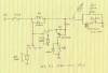
Here's the diagram i drew up:

Code:
12vdc -- fuse -- voltage switch - (>8V) -HORN -|
                       |                       |
                      (<8V) -- Relay ----------|
                                |              |
                       12vdc --- AIR HORN --|| |
                                               |
                                               |-- horn button --||
                                               |-- airhorn button -- resistor --||

my knowledge of electronics is very limited so if these questions could be answered:
1) will this circuit even work?
2) does a resistor placed just before ground lower the voltage of the entire circuit?
3) where do i find a switch that switches based on voltage
4) what resistor would i use to lower the voltage of the circuit down to <8v.

Any help would be greatly appreciated!
 
Try this: requires two 12V relays, three resistors, two diodes, and one transistor
 

Attachments

  • Horny.png
    Horny.png
    647.2 KB · Views: 221
i'm very confused about how that circuit works! can you please explain what exactly it does?

cheers
 
i'm very confused about how that circuit works! can you please explain what exactly it does?

cheers

When the REG HORN button is pushed, Relay K1 pulls in, sending power to the Reg Horn, and simultaneously removing power from the transistor. Ok so far?

If the AIR HORN button is pushed, K1 and the 330Ω are in series. The current is limited below what it would take to pull-in K1, but there is about a 2V drop across its coil. Current flows through K1's Normally Closed contact, to the emitter of the PNP, out the base and through the 100Ω resistor. That base current is amplified by the PNP whose collector current flows through the coil of K2 to ground, pulling it in, and powering the Air Horn.
 
I like it, but I'm easily amused, Reg horn button brings in K1 and removes power to Air horn, air horn button with resistor can't pull in K1, but is amplified to brings in K2 and air horn.
How about a 3rd device, more resistance in series with the button and higher gain amp or use comparators?
 
Here's a circuit that uses a 6V relay and a 12V relay without any electronics. The value of resistor R is selected to be approximately equal to the value of the two resistor coils in parallel.

When horn [1] button is pressed, relay K1 is pulled in and removes the power to relay K2. When horn [2] button is pressed, relay K2 is pulled in through the resistor. This keeps the relay voltages at around 6V so that K1 does not pull in.

You may have to play with the value of R some to get it to work properly, depending upon the relay characteristics.

For best results the two relays should probably be of the same design and manufacturer, differing only in coil voltage.
Horn.GIF
 
Here's a circuit that uses a 6V relay and a 12V relay without any electronics. The value of resistor R is selected to be approximately equal to the value of the two resistor coils in parallel.

When horn [1] button is pressed, relay K1 is pulled in and removes the power to relay K2. When horn [2] button is pressed, relay K2 is pulled in through the resistor. This keeps the relay voltages at around 6V so that K1 does not pull in.

You may have to play with the value of R some to get it to work properly, depending upon the relay characteristics.

For best results the two relays should probably be of the same design and manufacturer, differing only in coil voltage.
View attachment 31479

thanks! that's the same design i came up with but i'm wondering what's the most effective way to drop the voltage from max 13v to approx 3-6v which should be enough to trigger the second relay. i looked up a simple in series resistor, diode and even the L78S05. What's the best method? A drop in a fixed value of 6v is a sure win i think, so would i go with the diode route?
 
You could use a 6V or 7V zener in place of R.

The zener would require a sufficient power rating to carry the current of the two relay coils in parallel at 6V across the two coils.
 
Status
Not open for further replies.

Latest threads

New Articles From Microcontroller Tips

Back
Top