Continue to Site

Welcome to our site!

Electro Tech is an online community (with over 170,000 members) who enjoy talking about and building electronic circuits, projects and gadgets. To participate you need to register. Registration is free. Click here to register now.

  • Welcome to our site! Electro Tech is an online community (with over 170,000 members) who enjoy talking about and building electronic circuits, projects and gadgets. To participate you need to register. Registration is free. Click here to register now.

TVS question

Status
Not open for further replies.
Hello. I have what is probably a fairly simple question, but a question nonetheless seeing as I know very little to nothing about transient voltage supression and the few components used for this.

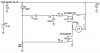
What I've got is a fairly large capacitor bank of which is rated (16v, 20v in a surge), a couple of MOSFET transistors of which are rated at a level that I do not believe require protection, and a 555 timer delay circuit.

My question is, would it be better to protect the bank using a TVS diode, a MOV, or does the bank even require protection at all? My plan is to place the device across +Vs and 0V.


the circuit in question can be found here: https://www.electro-tech-online.com/attachments/mosfet-switch-jpg.42663/
--Note, the FET's part #s have since changed.


Thankyou for your help in advance!
 
+Vs and 0v of WHAT? There is no question if we don't know the device and application this is going to be used it. Transient suppression is HIGHLY application specific.
 
Sorry, I was being pretty general.
My initial thought with this is to protect the capacitor bank from possible voltage spikes either with a MOV or a TVS Diode placed parallel to the capacitor bank itself.

This circuit is meant to be the wiring within an airsoft replica, giving the motor driving the thing Active Breaking and hopefully an increased rpm.
 
When you turn off the power to the motor, it will generate a voltage until it stops spinning. If you had some way of putting that power back onto the supply, you could get an increase of voltage. However, your circuit cannot use that power, so there isn't a problem. Even so, the battery would just absorb the power without the voltage rising much.

There are a couple of other things that can cause a problem in your circuit. Firstly, the inductance of the motor will be large, so the current in it cannot stop instantaneously. You need a path for that current. The body diode in Q2 will provide that path, but you could destroy Q1 if Q2 isn't fitted. 555

If you want to slow down the motor quickly, Q2 will short it out and will do that for you. You don't really need the, because a big capacitor feeding the gate of Q2 would turn it on for long enough, and it doesn't matter if Q2 turns off slowly, as the motor should have been stopped by then.

R6 needs to be much smaller than R1. When you release the trigger, R1 and R6 form a potential divider, and so the trigger input won't go below 1/2 the supply, so it won't trigger. There is no advantage of having R6 large, as it only wastes energy when the trigger is pulled, which is when a big motor is running anyhow.

You should also put a small resistor, maybe 470 ohm, in series with R3, otherwise, if you turn it to zero resistance, a lot of current will flow.

You won't get a higher motor speed than you can get connecting the motor directly to the battery, and you won't recover any motor energy without a seriously complicated circuit.
 
You won't get higher speed but you may get slightly higher starting torque because the capacitor bank will provide a little extra current at the start, but it won't be significant enough to justify the circuit or increased size. If you want more power, redesign the battery pack to include one extra cell. What advantage does electronic braking give you?
 
Last edited:
The active breaking function reduces some of the stress placed on the gearbox that the motor itself drives. Mechanically, when the trigger is released (when the Airsoft rifle is used in semi-automatic mode) it depresses the trigger contacts after one cycle. However, without active breaking, all of that left over angular momentum begins winding the gearbox a little bit again, increasing the force exerted by the internal spring, increasing wear on the mechanical components.


I have tried this out before with a few capacitors, and from what I've seen it increases the initial angular frequency of the motor when it starts up, hence why they are a part of this design. I was just worried that the initial voltage created by the motor when it becomes a generator would be damaging to the circuit.

I do like the idea of a capacitor feeding Q1's gate being the delay between switching from off to on, though i would have to make sure it only allows the P-MOSFET to be on for about .05s so that the user input on the switch does not overlap.

I know that this is kinda leaning off of the topic, but attached here is the circuit ajusted from Diver300's comments, along with where I would place a TVS diode. C2 would create the delay as Diver300 was saying preventing Q1 from being on when Q2 is on during the trigger pull. Correct me if I'm wrong, but my thought process for C3 is that it will create the delay needed when the trigger is released.

I know these here are just a few more questions, but:
Is my thought On C3 correct, and is the TVS Diode something that is even needed for this circuit?


Thankyou again guys for your input/suggestions!
 

Attachments

  • mosfet switch.jpg
    mosfet switch.jpg
    34.8 KB · Views: 154
Last edited:
Unless you change something in the motor (field strength, gearing, etc.), a DC motor cannot generate a higher voltage than that which originally ran it.

C2 leaves the gate of Q1 floating.

Switching transients from turning a motor on and off are too small to change the voltage on a 1 Farad capacitor.
 
Sorry, you'll have to forgive me, but when you say that Q1's gate will be floating are you saying that the voltage applied to Q1's gate will always be a positive value between 0v and 9.6v?
 
No it won't, it's capacitivly coupled, over time the gate voltage will be unknown, IE a positive pulse may not turn it on all the way, or a negative pulse may not turn it off all the way, you could stick the FET in it's linear range and toast the mosfet. This looks like a very poor attempt at something that will act like an h-bridge, but in practice fail badly. You need a proper h-bridge.
 
Alright, so that schematic then is a dud, but I'm not really sure how an H-bridge would do any good (unless what you are describing is an IC that creates the delay I need). The motor does not need to change it's direction. Simply turn in one direction on and short itself when it is off (infact, putting it in reverse would have quite a negative effect to the gearbox it drives)

The only issue I am having with this design is creating the timing delay between turning the MOSFET's on/off, seeing as everyone thus far is saying I do not need to worry about Transient voltage with these circuits.

I'm going to experiment with the schematic using the 555 timer with Diver300's suggestions before soldering a board or anything permanent. I've got spare components in-case anything frys.

Thankyou to everyone here for your comments/suggestions/help!
 
I know that you really really need to have a TVS when you have an inductive load. If you are controlling a motor, I believe you will have to have a TVS across the supply output.
 
Status
Not open for further replies.

Latest threads

Back
Top