Continue to Site

Welcome to our site!

Electro Tech is an online community (with over 170,000 members) who enjoy talking about and building electronic circuits, projects and gadgets. To participate you need to register. Registration is free. Click here to register now.

  • Welcome to our site! Electro Tech is an online community (with over 170,000 members) who enjoy talking about and building electronic circuits, projects and gadgets. To participate you need to register. Registration is free. Click here to register now.

question about speaker crossover

Status
Not open for further replies.
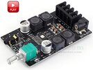
I am making a really simple cheap speaker (consisting of bluetooth amplifier ZK-502C, Dayton audio TCP115-4 and Dayton audio ND16FA-4) and i need a capcitor to cut low frequencies for tweeter. Usualy i used a electrolytic or ceramic capacitor to cap it at around 3500Hz. But today i read a guide on crossover and both types of capacitors are said to have negative effect on audio quality. The summary of the guide was that it is best to use film capacitors. Since i never dealt with them before i am looking for some help in choosing the right one.
 
The summary of the guide was that it is best to use film capacitors. Since i never dealt with them before i am looking for some help in choosing the right one.
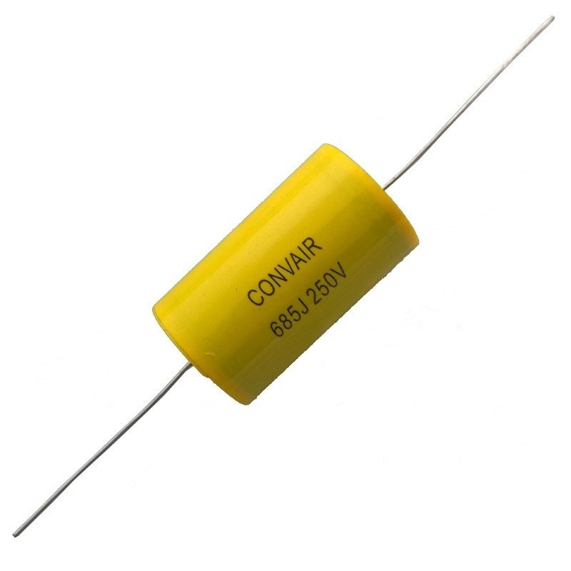
Any film or metalized film capacitor with any type of film material should work fine.
Parts Express, for example, has a good selection.
 
I am making a really simple cheap speaker (consisting of bluetooth amplifier ZK-502C, Dayton audio TCP115-4 and Dayton audio ND16FA-4) and i need a capcitor to cut low frequencies for tweeter. Usualy i used a electrolytic or ceramic capacitor to cap it at around 3500Hz. But today i read a guide on crossover and both types of capacitors are said to have negative effect on audio quality. The summary of the guide was that it is best to use film capacitors. Since i never dealt with them before i am looking for some help in choosing the right one.
As you're making a really cheap speaker any such concerns are a complete waste of time.

Even in top end (VERY expensive) speakers it's highly unlikely there would be any audible difference.
 
Any film or metalized film capacitor with any type of film material should work fine.
Parts Express, for example, has a good selection.
Ok, so if i do a search on aliexpress, i say film capacitor and the uF rating is the same as if i was searching for electrolytic or ceramic capacitor ? In my case its usualy around 7uF. How about voltage, i usualy use 25 or 30V if i supply my amplifier with 25V, but if i remember correctly u really need only something like square root of that voltage which would be about 5V ? Or maybe 7V to be on the safe side ?

As you're making a really cheap speaker any such concerns are a complete waste of time.

Even in top end (VERY expensive) speakers it's highly unlikely there would be any audible difference.
Thank you. I will check prices of film capacitors and if they are to high, i will just use the usual electrolytic or ceramic capacitors. Btw i saw you can also make a non polarized electrolytic capacitor using 2 polarized ones. Simply connecting the negative poles together. and then the uF rating is /2 of the original capacitors, in the case of connecting 2 10uF capacitors, the capacity of the duo will be 5uF. This would be neat since i have tons of polar capacitor lying around. But there are probably negative effects compared to simply using 1 non polar capacitor ?
 
Ok, so if i do a search on aliexpress, i say film capacitor and the uF rating is the same as if i was searching for electrolytic or ceramic capacitor ? In my case its usualy around 7uF. How about voltage, i usualy use 25 or 30V if i supply my amplifier with 25V, but if i remember correctly u really need only something like square root of that voltage which would be about 5V ? Or maybe 7V to be on the safe side ?


Thank you. I will check prices of film capacitors and if they are to high, i will just use the usual electrolytic or ceramic capacitors. Btw i saw you can also make a non polarized electrolytic capacitor using 2 polarized ones. Simply connecting the negative poles together. and then the uF rating is /2 of the original capacitors, in the case of connecting 2 10uF capacitors, the capacity of the duo will be 5uF. This would be neat since i have tons of polar capacitor lying around. But there are probably negative effects compared to simply using 1 non polar capacitor ?

It's commonly done in speaker crossover networks - in fact I suspect the (expensive) non-polarised electrolytics you can buy are actually just two back to back normal ones inside.
 
So doing that (connecting 2 polar capacitors) can actualy be better soundwise than single non polar ? Do you maybe know where i could find some data on that cause im interested in it, or if you maybe know :)
 
So doing that (connecting 2 polar capacitors) can actualy be better soundwise than single non polar ?
No.
But you will likely be unable to hear any difference between the two with your speakers, assuming you don't have the proverbial "Golden Ear" (those that can hear the difference between a normal power cord feeding the amp, and a super expensive, shielded, no-oxygen copper, power cord).
 
Thanks for the answers. I would open the new thread but since this one is also opened ... maybe u can help me understand something that is really bugging me - not so much money wise (i can always buy a new amp) but technically.

I am using a super cheap 2x50W amplifier that, to my uneducated ear, sounds very pleasant. Before that i used another amplifier of the same chinese brand that was also 2x50W, the difference being the old amplifier used a no name chinese amplifier, while this one uses TPA3116. I cant notice any difference in sound quality between them but i do notice that the TPA3116 has a little bit more bass, even the woofer movement is seen more.


The problem i am having with this particular amplifier is that when i turn the volume to high in certain songs, the bluetooth will disconect and reconnect. Now my gut feeling is that ok, amplifier uses to much juice and there is not enough juice for bluetooth and it disconects (restarts). But it doesn't make any sense considering that i am using 10A batteries (6S, 25.2V, 10A) and also i soldered about 4000uF worth of capacitors directly to the battery pack. This should cover any insane power demands right ?

Like i said, its not about money, its about knowing what exactly is going on. I would like to get to the bottom of this. Would a good start be to trace the power lines that go to the bluetooth chip and add a capacitor there ?
The old amp i used was ZK 502L - i didnt have problems running it at full power (i did occasionaly have problems when i turned it on and BMS triggered over current protection because battery pack was effectively shorted while charging the capacitors on amplifier. I solved that with a single 2000uF capacitor on battery pack). The new amp is ZK 502C. Both are said to be 2x50W. Speakers are TCP115-4 and ND16FA-4, both worked fine on old amp even on 100% volume. I would really like to stick with this amp cause otherwise i love it. But this disconecting is annoying. I am used to just being able to turn the volume up until i hear distortion and then lower it a bit until its comfortable. My old speaker with old amp worked like that for years like a charm.
 
Do you have a scope per chance ?

If so you could set it to trigger on an out of spec low V and see if playing music
any tranients cause supply to fall significantly. Same for a high trigger.

If you dont you could set up a comparator and drive a flip flop, or at minimum a LED
with a series R to limit LED current to say 5 - 10 mA when its on. Again looking for
either out of spec low and high voltages.

Power the comparator from a separate supply, like a 9V or two of them in series 18V
battery.

Regards, Dana.
 
I dont have any of those instruments sadly, all i have is a multimeter. I am playing a certain song (machinehead - imperium) and at like 36 second the song is suddenly ultra loud and hard. After a second or two you hear music kinda stops/restarts and then the amplifier turns off and on again. I tried adding like 5000uF worth of capacitors directly to amplifier input, didnt help. When the loud part comes, the voltage on amplifier input drops from 24V to like 23.6V but never goes lower. It is possible that my multimeter is to slow to detect this so i will try with some other small led voltage meter which is a lot faster in detecting this.


I have a question. This amplifier uses 2 470uF capacitors DC capacitors. I was wondering, what would happen if i added another capacitor in parallel to it ? Like 2000uF ? I am trying to make sure its not shutting down because it runs out of juice, but what would an effect be on speaker sound quality, would it even be usable ?
 

Attachments

  • 14855_0_3454.jpg
    14855_0_3454.jpg
    175.1 KB · Views: 298
danadak Nigel Goodwin rjenkinsgb
Ok the most amazing thing just happened. I did some more testing with the amp, nothing helped (adding 2P battery pack, adding 6K uF caps, etc.). In the end i just disconected the speakers altogether and the amplifier still disconected !

But here is when the most amazing thing that ever happened to me. Speakers were disconected but when the loud part came, suddenly i could hear the music, it was very silent but i clearly could distonguish which part of the song it is !! I thought maybe it was coming from my phone, or maybe i was hearing things. But no, it came from the amp itself !!!!

Whats goin on ? Clearly this is a faulty amp but how can it play music without speakers ??

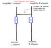
To make your search easier ... its probably my fault. Months ago i wanted to turn this amplifier from mono to stereo. I followed the instructions from this forum clearly - bridged the 2 channels together and then made sure each channel (line between amp and receiver) had some added resistance so that i would protect the channels from eachother. I did however use a very little resistance in order to get as much loudness as possible. Guide said like 100 ohms. I used like 10 ohms.

Speaker is still working mostly, except at certain songs at high volume. I will just replace the amp but now im curious whats goin on :))

Video i recorded of amp playing music without speakers:
 
I've no idea what you're on about, and you don't seem to understand what 'stereo' and 'bridging' are about, as they are completely different things. Nor do I have any idea what the resistors are for? - but it sounds like whatever you're doing is complete nonsense?.

As for sound with no speakers, as it's a class D amplifier it's not unusual to get audio from the filter coils on the output.
 
This is how i was told on this forum its supposed to work. Btw, it would be nice if people of authority on a forum whose sole purpose is the exchange of knowledge would say, "i am sorry, i dont understand what you are doing, can you clarify so i can help you" instead of throwing discouraging sentences at me.
 

Attachments

  • stereo into mono.png
    stereo into mono.png
    10.3 KB · Views: 292
I dont have any of those instruments sadly, all i have is a multimeter.

Here is a way of getting a PC based sound card oscilloscope. You have to be studious
and make sure you read how others have protected the sound inputs so no damage
occurs. This will give you a oscilloscope, spectrum analyzer, and basic signal generator.


.
PC Oscilloscope

artalabs.hr

roomeqwizard.com

https://www.zeitnitz.eu/Scope_en


If you do not have a scope here is a low speed freebee -

You can start with a PC sound card based scope for free. Will give you basically
audio range scope, spectrum analyzer, and function generator all using your
PC sound card. It may not be fast enough to handle the character LCD interface
however.


https://www.zeitnitz.eu/scope_en


http://www.zelscope.com/


http://www.ledametrix.com/oscope/


http://www.virtins.com/downloads.shtml


But first build a simple circuit to protect sound card inputs so you do not
ruin from transients, overvoltage. Google "protect sound card input".


For example http://makezine.com/projects/sound-card-oscilloscope/


A real inexpensive Logic Analyzer/pc combo can be had with this -

https://www.ebay.com/itm/USB-Logic-...h=item33f2ef28ec:g:NNoAAOSwjXVaoiyH:rk:4:pf:0

There are many vendors of this on ebay.

You download and install Saleae software to run it. https://www.saleae.com/downloads/

Sound card impedance bridge -

http://www.marucchi.it/ZRLC_web/ZRLC/Steber_An_LMS_Impedance_Bridge.pdf


http://www.sillanumsoft.org/ZRLC.htm


Regards, Dana.
 
This is how i was told on this forum its supposed to work. Btw, it would be nice if people of authority on a forum whose sole purpose is the exchange of knowledge would say, "i am sorry, i dont understand what you are doing, can you clarify so i can help you" instead of throwing discouraging sentences at me.
As I said at the time, no resistors needed - they are completely pointless.

However, the issue is you mentioned 'converting to stereo' and 'bridging' - both of which are completely wrong.

Shorting the inputs of two stereo amps together simply converts the stereo to mono - nothing else - and is what the mono/stereo button on some VERY old stereo amps did.
 
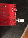
Ok i found the topic where members suggested me to use the resistor. They said without a resistor, there can be some distortion when the amplifier is turned all the way to 100% (which is how i use it). And someone said that without resistors, if only 1 channel is sending the signal in, and another isnt, then some juice can flow from L channel directly into R channel and causes damage to the receiver. Here is the thread:


But if you say its alright just shorting L and R, i will do that, its simpler for me. Does it matter if i short it before or after the pot ? Right now i shorted the channels after they came out of the pot.

IMG_1582.JPG
 
You are blending the two input channels using a couple of low value resistors, which is fine.
They are to protect the output amps on whatever is feeding your power amplifier.

A direct short is OK at a non-power stage but I'd leave it as it is to run from the audio out on another device, which could well be headphone level amps.

It's not related to the problem with the amp shutting down in any way, other than confusing the terminology so things went off at a tangent.

The critical point is how you are using the two channel outputs of your amplifier board?

If I remember right, originally one channel fed the main speaker and the other the tweeter??


ps. For info, the TPA3116D2 ICs are "Class D" amplifiers; effectively a full H bridge PWM output for each channel, switching at anything from 400KHz to over 1 MHz, then the outputs filtered to remove most of the switching frequency by the big inductors and caps on the PCB.

The inductors are likely vibrating slightly with the current through them, and that is what you can hear with no speakers connected.
 
Status
Not open for further replies.

Latest threads

New Articles From Microcontroller Tips

Back
Top